Continue to Site

Welcome to EDAboard.com

Welcome to our site! EDAboard.com is an international Electronics Discussion Forum focused on EDA software, circuits, schematics, books, theory, papers, asic, pld, 8051, DSP, Network, RF, Analog Design, PCB, Service Manuals... and a whole lot more! To participate you need to register. Registration is free. Click here to register now.

Gain of inverting amplifier using OpAmp

Status
Not open for further replies.
E

expertengr

Guest
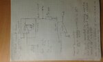
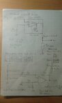
I need to invert the polarity of the voltage across PT1000 from -0.548 V to +0.548 V using an OpAmp AD844 in unity gain inverting configuration. The output of the inverting amplifier is Vout = -(R2/R1) Vin, where R2 is the feedback resistance. If I use R1 = R2 = 1K Ohm, the output of the OpAmp is only 0.250 V which shows that gain approximately half instead of 1. In order to get approximately +0.548 V I need to use R2 = 2.2 K Ohm feedback resister. I am wondering why the unity gain does not work to convert -0.548 V to +0.548 V ?
 

Hello!

Since it's your first post:

- You may consider to say hello.
- When you ask a question, you may also consider using these words: please, thank you.
Even if you don't know what it means.
- What you explain is difficult to read. You may consider sending a drawing of what you are testing,
it would be better than trying to explain what is R2.

It's so much easier with a schematic and you would need about 1/3 of the above explanations.

Dora.
 

I guess file is uploaded.

op-amp_basic_inv.gif
 

HI,

no wonder it doesn´t work, your circuit has no supply.

Additionally: A PT1000 doesn´t produce voltage, it is just a variable resistor. To get voltage you need any circuit. But you didn´t show.

***
I assume.. when you see the output to be only 0.25V (at a powered Opamap), and you measure the voltage at R1 you will see -0.25V.


Klaus
 

In the file attach above, the input in the circuit is -0.548 V, R1 = 1 K Ohm and R2 = 1 K Ohm. This should give +0.548 V as output theoretically but I measure 0.250 V which is approximately half of the theoretical. Please help me to understand the reason for this half gain. Thanks in advance for your explanation and your comment on this post.

- - - Updated - - -

Thanks Klaus for your reply. The chip AD844 was powered up correctly with Vs(+) = +12 V and Vs(-) = -12 V. The resistance of PT1000 change with temperature but at a constant temperature it should have constant resistance and a voltage across the PT1000. I measure -0.548 V across PT1000 and I would like to invert its polarity from -0.548 V to +0.548 V. But unity gain inverting amplifier gives +0.250 V.
 

Frankly I think you should add one buffer before the gain OPA. As KlausST suggested the PT1000 is a variable resistor and you will get the voltage signal if you supply the PT1000 with the constant current source. Anyway the voltage signal will be varied if the input resistance of the next gain stage would not be high enough. as you know it has the load effect. generally the buffer would be keep the voltage signal constant and then the next gain stage would amplify your voltage signal to your desirable range.
 

Thanks max.wangxin.sh for your reply. I would like to add some more information. I generate a current source of 0.5 mA using an Op Amp which I am feeding to PT1000. The resistance of PT1000 can be calculates as (-548 mV /-0.5 mA = 1097 Ohm) which corresponds to 25 C and this match with reference temperature in the lab. The task is to convert -548 mV to +548 mV.
 

Hi,

show the complete circuit including PT1000 and current source with voltages and all device values.

Klaus
 

The input resistance of your inverting amplifier is 1k ohms which attenuates half of the input voltage from your 1k ohms sensor that needs a load of at least 100k ohms. That is why you were told to add a buffer between the sensor and the inverting opamp circuit because the buffer can have an input resistance of 100k ohms or more.
 

If you don't want to ruin the Pt1000 characteristic, an amplifier with infinite input impedance (respectively a buffer in front of your amplifier) must be used.

The problem had been clear from the start with sufficient circuit information. Please remember for your next posts.
 

Kindly see my circuit in attachment.
 

Attachments

  • 20160917_202418.jpg
    20160917_202418.jpg
    277.3 KB · Views: 132

Hi,

As assumed before your inverting opamp circuit influences the Pt1000 voltage.
--> as soon as you connect Vpt to R6 the voltage Vpt changes from -0.548V to -0.250V.

****
The "bilateral" current source is more than you need, because a simple current source is sufficient.
But in this case maybe you can connect R1 to -12V instead +12V, then the PT1000 output is positive...

No inverter needed anymore, but a buffer could improve performance.

Klaus
 

    V

    Points: 2
    Helpful Answer Positive Rating
The current source schematic is flawed. Output wrongly connected.

I agree with KlausST. An unidirectional current source with FET output transistor is less sensitive to resistor tolerances. Making a positive current source allows non-inverting amplifier with high input impedance.
 

Thanks KlausST and FvM for your valuable comments. I will replace +12 V to -12 V at R1 in the bilateral current source. This will change the current direction. Then I hope I will measure Vpt +0.548 V across PT1000 instead of -0.548 V. Then obviously inverting amplifier will not be needed.

I mentioned before that (0.548 V / 0.5 mA) = 1097 Ohm corresponds to 25 C temperature which match with the reference temperature.

My requirement is to measure temperature from -70 C to +180 C using PT1000. In the attached file there is a table which shows that the voltage across PT1000 with 0.5 mA current source should vary between 0.360 V to 0.842 V. I need to scale this voltage (Vpt) from 0 to 5 V for microcontroller. This means I need to subtract 0.360 V from Vpt and then amplifies with gain 10.5 to get 0 V to 5 V for -70 C and 180 C respectively.

Kindly review my circuit in the attached file where I generate 0.360 V from voltage divider using two resistances and then I use a difference amplifier with a gain of 10.5 such that Vout = (Vpt - 0.360 V) x 10.5. I will try this circuit but I am not sure if there is something missing regarding impedance. I need your review and comments again which will be very helpful to me. Thanks in advance.
 

Attachments

  • 20160918_192633.jpg
    20160918_192633.jpg
    269.5 KB · Views: 131

Hi,

I need to scale this voltage (Vpt) from 0 to 5 V for microcontroller.
Don't go to the limits. Use a bit safety margin. Do the rest with software.

Circuit:
Don't make the same mistake again: your difference amplifier has not infinite input impedace, therefore it will modify the sensor voltage.

Klaus
 

@ Klaus, could you please give me an example of buffer that I should put between sensor output and amplifier. I guess this is to set low output impedance before it goes to amplifier with high impedance input.

I am also wondering that what is the safety margin for AD844, is it something like 0.2 V to 4.8 V if powered up by +5 V and -5 V. Secondly, the output signal from PT1000 as shown in the attached file before, varies between 0.360 V and 0.842 V. I want to amplify this signal to acceptable full range within 0 V to 5 V with safety margin. How to make the infinite input impedance of difference amplifier.
 

Hi,


buffer is explained above. You know the input and output voltages. Input impedance is given in each datasheet. Output voltage range is given in each datasheet.
I know it´s easier for you if someone else is reading datasheets. But I recommend to do it on your own. All is explained in the posts above.

Now you changed the supply voltage. We dot know why. This generates a different situation with new requirements for the amplifier. The AD844 can´t be used.
I recommend to use a RR in RR out OPAMP. Almost any cheap will do.

Klaus
 

    V

    Points: 2
    Helpful Answer Positive Rating
Now it works. Thanks KlausST and FvM. I able to scale the Vpt using a difference amplifier.
 

Status
Not open for further replies.

Similar threads

Part and Inventory Search

Welcome to EDABoard.com

Sponsor

Back
Top