Continue to Site

Welcome to EDAboard.com

Welcome to our site! EDAboard.com is an international Electronics Discussion Forum focused on EDA software, circuits, schematics, books, theory, papers, asic, pld, 8051, DSP, Network, RF, Analog Design, PCB, Service Manuals... and a whole lot more! To participate you need to register. Registration is free. Click here to register now.

Common Ground question

Status
Not open for further replies.

xmen_xwk

Full Member level 3
Joined
Sep 12, 2014
Messages
172
Helped
2
Reputation
4
Reaction score
2
Trophy points
18
Activity points
1,373
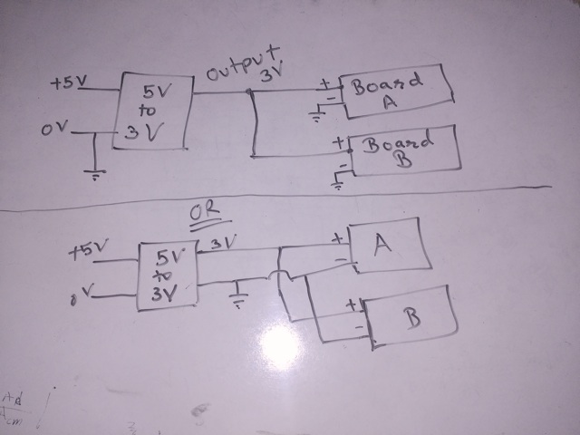
I have a 5V supply powering 2 boards.
Both boards also require 3V power. Im using one voltage regulator on board B, and giving a 3V wire connection to board A.

While both boards have same GND connection from 5V power supply. Should I give another GND wire along with 3V ? If I do it will create ground loop, right ? So which one is better ?

quick draw.png
 

Hi,

It depends.
It depends on power requirement of both boards and if there are other connections between both boards (analog signals, digital signals...)

With low power supply and no other connections i`d cut the GND line to the upper board and put it in parallel to the 3V line.

Klaus
 

all boards required one ground not many ground.

ground has only one voltage which is common for all elements .

you can connect it by two ways.


as per description, you are connecting both boards to +5 volts. which can damage.
 
Last edited by a moderator:

Let me clear things bit more. Both boards need 5v and 3v. Yes there are logic connections of 3v between both boards. So in that case should I add another wire for GND along with 3v ?
 

Hi,

2 boards using the 5V and the 3V? The regulator depends on the 5V ground, if I've understood correctly? So the 3V is a "child" of the "parent" 5V or whatever you want to call it? So you shouldn't need an additional ground cable, I think, because surely the regulator ground is the same potential as the 5V shared ground, as the regulator ground is the original 5V supply ground, so both boards share the same ground, regulator or not.

Another matter may be how the 3V cabling from board B to A may need to be done, I'm not up on shielding and so on.
 

Since the 3V ground and the 5V ground are the same, just run ONE low impedance ground to the other board. Otherwise, you do risk ground loops.
 

Hi,

If you read about EMC you will find out you should install power lines (3V, 5V...) in close proximity to the return path (GND).
The same is for signal lines.

This reduces inductivity and impedance.

Additionally this reduces the loop to be an antenna. It reduces sending out electromagnetic waves as well as receiving electromagnetic waves.

Klaus
 
Untitled-1.png

Should I add ground wire between U1 and 3V LDO ? or one Ground wire is enough that is outside the board. I could just add the wire but I think it will create ground loop.
 

Hi,

One reason to add the ground line from 3V LDO to U1 is for better line sensing/voltage regulation, from stuff I read in app notes, where you connect load ground connection point to LDO ground connection point, not sure how you do that with two loads. I'd understood that signal return paths should be as short as possible.

In my ignorance, I still don't see much point in adding a second ground cable between two boards already ground connected, 'though.
 

Should I add ground wire between U1 and 3V LDO ? .

The answer is, IMHO, a bold NO. But you should also pay attention to the comment and suggestion made in #7. If you care for EMI and noise pickups, you should run the 3V cable in close proximity with the 5V cable and ground.

If you have signal (analog) that are noise sensitive you should consider a star connection for all the local grounds.
 
Hi,

You ask the same question again and again, but it is at least answered three times clearely in different posts.

Klaus
 

The best answer would result from a better understanding of the signals and ICs in question but people have given you the correct general response. No. Avoid the ground loop.

Note that you have another option which is to connect the boards serially. So 5V/Gnd goes into the first board and then that board sends 5V/3.3V/Gnd to the second board. This creates a direct connection between the two communicating boards without creating a loop.

In practice I might provide provisions for every option with 0 ohm resistors populated or not (run a ground wire along with your signal but only terminate it at one end for example).
 

Status
Not open for further replies.

Similar threads

Part and Inventory Search

Welcome to EDABoard.com

Sponsor

Back
Top