Continue to Site

Welcome to EDAboard.com

Welcome to our site! EDAboard.com is an international Electronics Discussion Forum focused on EDA software, circuits, schematics, books, theory, papers, asic, pld, 8051, DSP, Network, RF, Analog Design, PCB, Service Manuals... and a whole lot more! To participate you need to register. Registration is free. Click here to register now.

Why boost converter is showing 54V instead of 40V

Status
Not open for further replies.

Ganesan_R

Junior Member level 1
Joined
Sep 1, 2016
Messages
16
Helped
0
Reputation
0
Reaction score
0
Trophy points
1
Activity points
237
Dear Sir,

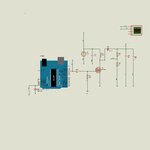
Pl. find attached the Arduino dc boost converter boost converter proteus simulation file and program.

I wanted the output to settle at 40V, but it shows variation between 48V-54V of course at switching frequency.

Of course PWM frequency is alright at 65kHz.

The relevant code is:

Code:
void loop() {
  // put your main code here, to run repeatedly:
  
 
   actualVoltage = analogRead(A5)*(4.9/1023)*(160/20);
    
   
   if (actualVoltage>(desiredVoltage+0.5)) 
        {
        OCR2A--;
        }
  else if (actualVoltage<(desiredVoltage-0.5)) 
        {
        OCR2A++;
        }
   
   }
Any help will be deeply appreciated.

Thanks.

Yours sincerely,
R. Ganesan.
 

Attachments

  • doubt_1.txt
    710 bytes · Views: 60
  • doubt_1.jpg
    doubt_1.jpg
    461.5 KB · Views: 87
Last edited by a moderator:

How can you regulate 40V with a maximum measurement range of 4.9*8 = 39.2 V?

The code is implementing a hysteretic I controller which is potentially unstable, at least must show an oscillating output.
Did you test it's operation with a lower set point, e.g. 20 or 30V?

There should be limiting means to avoid OCR2 overflow.
 

Dear FvM,

I thank you for your kind reply.

Your first point is correct can only achieve 39.2V.

To me output oscillations look like oscillations around switching frequency. The output oscillates between 48-54V as already noted.

I did not test it with lower voltages.

I do not understand how to make hysteresis loop stable. Why hysteresis loop is inherently unstable?

I will google OCR2A overflow and how to prevent it. Any useful links will be appreciated.

Thanks.

Yours sincerely,
R. Ganesan.
 

Hi,

additionally a zener (D2) is not a good overvoltage protection in an analog measuremt path.

you think a 4.7V type is high impedance from 0..4.7V and then immediately low impedance above 4.7V. But when you read the datasheet (we all need to read datasheets) you see that even at 4V you can expect a current of about 0.1mA.
Without zener 4V at the ADC means 32V at the output.
With zener 4V at the ADC means about 46V at the output. an error of 14V!!!.

--> In your case I´d say you don´t need any protection. 1mA for a short time should be no problem. But 1mA means more than 140V at the output. Unlikely.

I´d lower the ADC source impedance by using 3k and 21k or similar..

Klaus
 

Saying you have "oscillations around switching frequency" means your output filter doesn't work. Or you are not probing the output voltage correctly. Is it a breadboard design?

Regarding the (actually superfluous) zener diode and numerical 39.2V limit: Try with 20V set point. The output voltage should be at least regulated on average.
I will google OCR2A overflow and how to prevent it. Any useful links will be appreciated.
I would suggest thinking instead. What's the useful range of OCR2A (also depends on the unknown timer setup), which basic C operation can avoid increment or decrementing it beyond useful limits.
 
Hi,

indeed it sounds like a breadboard :-( ....In my eyes a breadbord is almost useless for switching applications. Especially with power applications.

And the 100u sounds like an electrolytic one. There are cheap 100u electrolytics just form mains frequency applications. And there are electrolytics for higher frequency switching applications. Be sure to choose the high frequency one. And calculate wich ESR you can tolerate.

Klaus
 
Dear KlasuST and FvM,

Your answers solved my issue.

With FvM, I changed the parameters so that increment and decrement is not beyond useful limits.

Thank you KlausST for enhancing my understanding.

With confidence I will now try my hands on dc/ac inverter.

Yours sincerely,
R. Ganesan.
 

Status
Not open for further replies.

Similar threads

Part and Inventory Search

Welcome to EDABoard.com

Sponsor

Back
Top