Continue to Site

Welcome to EDAboard.com

Welcome to our site! EDAboard.com is an international Electronics Discussion Forum focused on EDA software, circuits, schematics, books, theory, papers, asic, pld, 8051, DSP, Network, RF, Analog Design, PCB, Service Manuals... and a whole lot more! To participate you need to register. Registration is free. Click here to register now.

[SOLVED] Single power supply instrumentation amplifier using LM324

Status
Not open for further replies.

pravin b

Member level 5
Joined
May 20, 2012
Messages
85
Helped
2
Reputation
4
Reaction score
1
Trophy points
1,288
Location
Mumbai, India
Activity points
2,083
Hello friends,
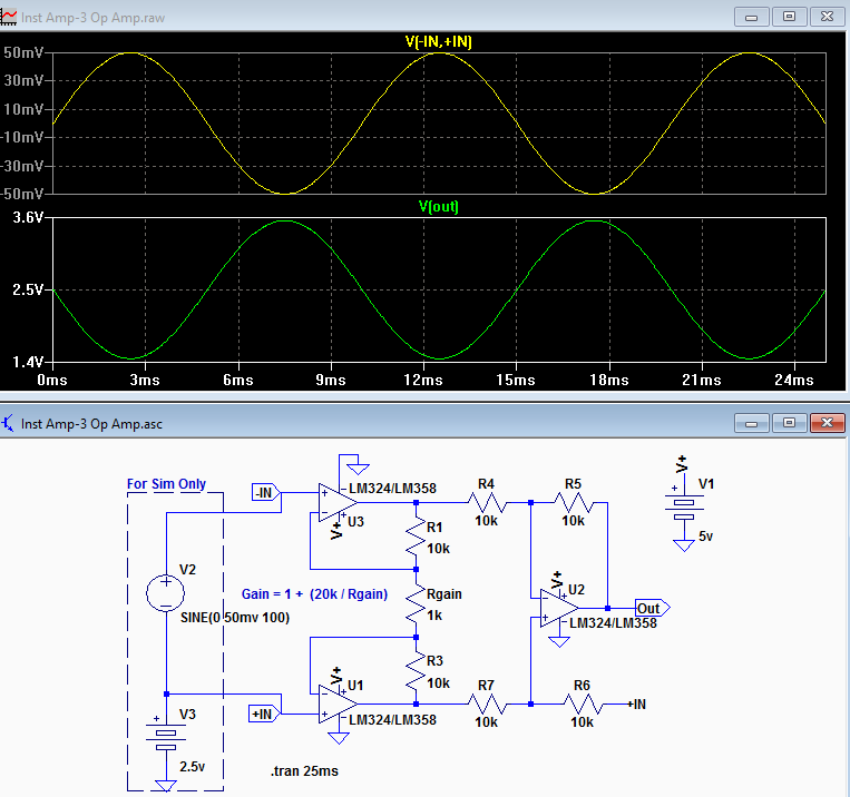
I am trying to design an instrumentation amplifier using LM324 (since it works with single power supply (as per datasheet), it is cheap and available in stock). However currently I am testing my circuit on proteus, but I am not getting the calculated gain &/or output using single power supply. whereas I am getting the calculated gain if dual supply to opamp is used. It would be helpful if someone can shed some light on this and suggest the modification to use it on single power supply.
Here is my circuit for reference. Untitled.png
 

Hi,

Can you specify the calculated gain and output for single supply, thanks, and the single and dual supply voltages you're using.
 
Hi,

I assume you just violate input voltage range and/or output voltage range.


Klaus
 
I really love these brainless Proteus schematics that hide essential information like supply voltage...

KlausST is surely right, the circuit can't work with single supply and the shown input voltages. A bit more of datasheet literature and circuit analysis is strongly suggested.

No accurate LM324 model seems to be true as well, U1A voltages are already implausible.
 
Oh sorry guys for not specifying supply voltages....
LM324 is powered with +5V at pin 4 and 0V at pin 11. as per calculated gain with the TF: gain=1+(2R/R1)=21 in previously uploaded circuit . where R1=R2=R4=R5=R6=R7=R=10K & R3=1K.
I am trying to amplify the difference between voltages applied to pin 3 & pin 5 (non-inv terminal) of LM324. But the problem is i am not able to achieve the calculated gain with the single power supply.
@d123: I have mentioned the parameters in this comment.
@KlausST, FvM: LM324 can take upto Single Supply 3 V to 32 V & output voltage swing is Vcc-1.5V
@AudioGuru: There is no need to power each of the OPAMP any one will do.
Thanks for being kind.

However correct results (i.e. gain and output) can be seen when i use dual supply like +5V at pin 4 and -5V at pin 11. Like can be seen in simulation file below.
Untitled.png
does it mean that LM324 can not work as an instrumentation amplifier with single power supply? or do i need to modify the circuit to make it work on single power supply?
 

Hi,

LM324 is powered with +5V at pin 4 and 0V at pin 11.
How can the output of U1:B be negative? It shows about "-2V".

Either your power supply is wrong, or the simulation is wrong.

Klaus

- - - Updated - - -

Added:

Do you need very high input impedance? Or is 10k Ok for you?

What is your real input voltage range for both your inputs?

Klaus
 

See you get expected G=21 with dual supply.
does it mean that LM324 can not work as an instrumentation amplifier with single power supply? or do i need to modify the circuit to make it work on single power supply?
It's not a LM324 problem. LM324 has input and output voltage range almost down to the negative rail, apparently not correctly modeled in Proteus. But the Proteus model bug is only a minor additional problem.

But even with perfect rail-to-rail amplifier, input voltages of +0.2/0 are outside the operation range of a G=21 single supply instrumentation amplifier. The voltage levels observed in the dual supply test clearly show why.

Instrumentation amplifier datasheets have usually a diagram showing the useable input and output voltage ranges for different gains and supply voltages. You can make a similar diagram for your circuit.

Do a bit more of circuit analysis...
 

@KlausST Actually the input voltage range for IN AMP will be 0-150mVolts from wheatstone bridge of a pressure sensor. Which is further will be applied to PIC ADC Input channel. As i read about INAPMs they gives very high impedance helping to reduce the noise in signal. Thats why I am trying to simulate the above circuit so that i can use it for my application. However I am not sure how much impedance would be sufficient for me? Can you help me in this regard too? Thanks for being patient.
 

Hi,

Actually the input voltage range for IN AMP will be 0-150mVolts from wheatstone bridge of a pressure sensor
I assume you talk about the "differential" input voltage range. But we need to know the absolute voltage range.

Usually with bridge type sensors you have a common mode voltage at about half of the sensor supply voltage.
What is your sensor supply voltage.

about INAPMs they gives very high impedance helping to reduce the noise in signal
First time I heared that high impedance should reduce noise. Maybe I´m missing some information..

However I am not sure how much impedance would be sufficient for me? Can you help me in this regard too?
It depends on your sensor impedance. --> Please tell us.

But usually this is not very cirtical. Even I 1k sensor at a 10k input impedance circuit...surely it will reduce the signal voltage a bit..but do you need absolute accuracy?
Often sensors are calibrated with software...then it does not matter.

***If you want to try: just use the difference amplifier circuit: U1C, with R5=R6 = 10k, R7 = R8 = 210k.
A low pass filter capacitor across each R7 and R8 may help to reduce hgh frequency noise.
What´s your sensor frequency range of interest?

Maybe you need a constant voltage at R7 as dedicated offset.

Klaus
 

Actually the input voltage range for IN AMP will be 0-150mVolts from wheatstone bridge of a pressure sensor.
How?
If it's a dual supply bridge, it has common mode voltage around zero, can be easily below zero as well.
If it's a single supply sensor, it has common mode output around Vcc/2, e.g. 2.5 V for a 5V supplied sensor.

In both cases, your test simulation doesn't match the expectable sensor output voltage range. Please reconsider.

Additional points. You should also look at bridge output impedance. For moderate accuracy requirements, a simple single OP, 4 resistor differential amplifier might be sufficient. On the other hand, LM324 offset voltage isn't negligible with 150 mV sensor output. You may want to look for a higher precision OP.
 

At pins U1:a -3 and U1:b-5 , give a dc 2.5v .
check the output.
 

Hi,

At pins U1:a -3 and U1:b-5 , give a dc 2.5v .
check the output.
confusing...

No, usually both inputs are close to 2.5V.
(The OP uses 0.2V difference voltage. This violates output voltage swing specificaton, because 0.2V x 21 = 4.2V, but specificaton says: V+ -1.5V wich is 3.5V only. )

Therfore let´s use 0.1V difference voltage:

let´s say upper is 2.50V, the lower is 2.40V (makes 0.1V difference) the output should be 0.1V x 21 = 2.1V

or
let´s say upper is 2.60V, the lower is 2.50V (makes 0.1V difference) the output should be 0.1V x 21 = 2.1V

or
let´s say upper is 2.55V, the lower is 2.45V (makes 0.1V difference) the output should be 0.1V x 21 = 2.1V

All this should work with true instrumentation amplifier circuit, single supply, as well as with the simple difference amplifier circuit, single supply.

Klaus
 

Pressure range :0-5 .8 psi (40kpa);
Product Features:
Solid, MEMS technology, high reliability
Low cost
Wide monitoring and control media
The application of a wide temperature range
Easy to use, choose from a variety of range. Easy to use, easy to install in OEM equipment
Application areas:
Automotive: tire pressure, car air pump, MAP sensor, diagnostic equipment, automotive sensors.
Industry: Air brake switch, portable pressure gauge, such as digital pressure gauge,
environmental monitoring, consumer and sports
Health care: patient monitoring and diagnostic equipment, such as blood pressure monitors,
medical instrumentation and monitoring
Range: 40kpa (differential pressure)
Output: mV signal
Electricity supply: 5VDC or constant current 1Ma
Linear accuracy: 0.25% FS

Measure the pressure range of 580 PSIG, 40KPaG
Max pressure capacity of three times the measuring range
Work power supply 5 VDC,
Input impedance of 4 - 6 KΩ
The output impedance of 4 - 6 KΩ
Operating temperature -40 - 85 ° C -40 ° F - +185 ° F
Storage Temperature -40 - 125 ° C -40 ° the F - +257 ° F
Accessible media, clean, dry, non-corrosive gases
Bias voltage ± 25 mV
Full-scale output voltage 50 - 100 mV
Bridge Resistance to 4 - 6 KΩ
Linearity ± 0.3% F.S.
Hysteresis ± 0.7% F.S.
Bias Temperature coefficient ± 0.08% of F.S. / °c
Temperature coefficient of sensitivity -0.21 % FS/ °c
HTML:
https://cdn.sparkfun.com/assets/home_page_posts/1/9/0/2/Pressure_Sensor.pdf

is the information i could get from the sensor datasheet.
@KlausST: yEs i meant to be differential voltage input to INAMP.
sensor is single supply bridge with 5 volts supply voltage and produces 50-100mV. for 0-40KPa with Input impedance of 4 - 6 KΩ
The output impedance of 4 - 6. So what would be the impedance i need? (may be 40KOhms???). Yes i will try with the difference amplifier design you suggested for sure and will let you know the results.

A low pass filter capacitor across each R7 and R8 may help to reduce hgh frequency noise.
What´s your sensor frequency range of interest?

Can you teach me how to calculate the value of the capacitance to be used? Also I should use the capacitor in parallel with R7 & R8, correct me if i am wrong. It will be great learning for me if you could tell me that how would i know the sensor frequency range?
Thanks for this learning opportunity KlausST.
Edit: however I tried simple difference amplifier with the gain of 10 ,single power supply of +5Volts and simulated the circuit for 0-100mV single ended supply (not differential, since i don't have any) input, on breadboard it worked fine, but i dont see any output when input is given from sensor, so i thought i should try IN AMP configuration. I assumed to pick up the signals in range of mV the difference amp may not be sufficient. By the way can you tell me how can I read the sensor's differential voltage value? and how can i simulate the differential voltage?

- - - Updated - - -

@FvM: the primary use of the above circuit was purely to understand the designing of INAMP circuit with LM324 using single supply voltage. I did not considered the sensor output until then.

But since now we are talking about the sensor, I have to amplify the sensor output (50-100mV) to usable level like 0-5 volts. Considering, I have to operate the circuit with 5V supply and output voltage swing of OPAMP is Vcc-1.5V, I think I should amplify 50-100mV to 0-3 Volts. Am I right? also i did checked the input offset volatge in datasheet is says 5mV for LM324.

Also it would me very helpful if someone can tell me how can i measure or check the differential output of sensor with change in pressure?

Thanks for being so nice guys!
 
Last edited:

Hi,

to answer your question I need the requested informations first. (please in this order)
but do you need absolute accuracy?
Often sensors are calibrated with software...then it does not matter.

Can you teach me how to calculate the value of the capacitance to be used?
You can find this information million times in the internet: RC low pass filter: fc = 1 / (2 * Pi * R * C)

if you could tell me that how would i know the sensor frequency range?
We don´t know your application.
* Maybe you want to analyze the pressure inside a motor, then the change is very fast. within milliseconds. Means you need kilohertz of frequency range.
* Maybe you want to measure natural air pressure. It will slowly change within hours. Very low frequency range. Means 0.01Hz
* maybe you want to measure the pressure of a compressed air system. It will change within seconds..minutes... Means maybe 0.1Hz ...10Hz.

By the way can you tell me how can I read the sensor's differential voltage value?
Use your amplifier..this one we are talking about.

how can i simulate the differential voltage?
connect three resistors in a string: GND --- 1k --- 20R --- 1k --- 5V (generates 49.505 mV across the unloaded 20R)
Additionally connect a 4k resistor from each 20R resistor to the two difference amplifier inputs.
This simple circuit should give about the same source impedance as your sensor.

Klaus
 

@KlausST:
1. Being a stand alone application for pressure measurement and control, generated by DC motor and controlled with solenoid valve, so i need absolute accuracy.
2. with above specified application my sensor frequency will be like in some KHz. (how can i figure out the exact one?)
3. As suggested by you in earlier comment I will try again with diff amplifier. with below circuit; gain=10. let me know if i have made it correct.
But with this circuit i am able to get expected output for differential voltage above 50mV. for voltages below 50mV i get unstable gain.
4. I have used the somewhat scheme to generate differential voltage of about 150mV as shown in simulation file.
Please correct me if I am following any wrong procedure.
Thanks.
ckt.png
here is the simulation results for range of inputs from 0V-120mV
Untitled1.png
please omit the gain figure for Vin=0V.
 

Hi,

the problem is you didn´t follow my recommendation for a simulation unit: 1k-20R-1k. Then two 4k resistors one from each 20R resistor leg to the difference amplifier inputs (= 40k resisors, see below)...
You may make the 20R adjustable 0...50R.

For sure your difference amplifier should have higher input impedance. 10 times the sensor impedance is a good start. so use 40k and 400k. (for gain = 10)

Klaus
 

Thanks for your reply. I think I am still not be able to catch the circuit with 4K resistors from 20R legs. Have i connected it correctly this time?
can you please send me schematic (in any form) if possible if i am wrong this time! Also with the RC filter for noise.
Thanks being so patient. I am trying to learn from you.

ckt2.png
 
Last edited:

I haven't read all the posts in detail but here is my LTspice simulation of the LM324 circuit.
Note the output is offset to 2.5V by the input to R6.


Hi,

The 4k is correct now.

Filter: use two 470pF and connect them in parallel to the two 400k.

I recommend to add a bit offset to the output to avoid problems when the output is near zero.
Maybe 50mV. You can subtract it in software.

Klaus
 

Status
Not open for further replies.

Similar threads

Part and Inventory Search

Welcome to EDABoard.com

Sponsor

Back
Top