Continue to Site

Welcome to EDAboard.com

Welcome to our site! EDAboard.com is an international Electronics Discussion Forum focused on EDA software, circuits, schematics, books, theory, papers, asic, pld, 8051, DSP, Network, RF, Analog Design, PCB, Service Manuals... and a whole lot more! To participate you need to register. Registration is free. Click here to register now.

[SOLVED] [moved] Logic & Latching Problem

Status
Not open for further replies.

kam1787

Advanced Member level 3
Joined
Jul 5, 2010
Messages
926
Helped
167
Reputation
340
Reaction score
168
Trophy points
1,323
Location
English
Activity points
5,825
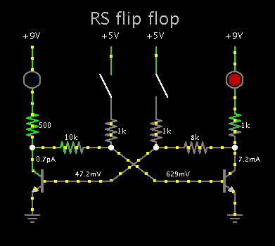
I need a [cheap and simple] latch [CMOS] to work as follows

1) two inputs, one output

2) upon a short logical high on input_1, output goes high and stays high Any other logic highs will make the output high

3) upon a short logical high on input_2, output goes low. Any other logic highs keep low


I am ok with simple logic gates but I NEED help with this! ideas?
 

Re: Logic & Latching Problem

The firs thing that comes to mind is two NOR gates in the same arrangement as done with an SR flip-flop to store trigger commands. Had you already performed some mental simulation with that kind of circuit ?


Re: Logic & Latching Problem

At least as far as I can see, the S and R signals at the truth table in that link seems like depicting exactly what you want to do with input_1 and input_2 NOT'ed.
 

Re: Logic & Latching Problem

RS flip flop made from cross-coupled transistors. Simple memory cell.

6517057100_1472424966.png


It can be adapted to operate the way you wish. Add diodes, change values, rearrange to use P devices, etc.
 

Re: Logic & Latching Problem

It should be remarked that the circuit that you described above do not appear to be a Latch.

How would you describe it?! I have no other terms to describe it...............it should go high when input_1 goes high and stay high

- - - Updated - - -

RS flip flop made from cross-coupled transistors. Simple memory cell.

6517057100_1472424966.png


It can be adapted to operate the way you wish. Add diodes, change values, rearrange to use P devices, etc.


You will have to walk me thru it................sorry but my brain seizes up when I try to walk thru it.

Ideally it should use CMOS logic......................
 

Re: Logic & Latching Problem

How would you describe it?! I have no other terms to describe it...............it should go high when input_1 goes high and stay high

You're right, I was seeing it as a simple flip-flop, but actually it is just an SR latch.
To be a flip-flop the output changes should be clocked.
 

Re: Logic & Latching Problem

You will have to walk me thru it

Sorry, I should have stated that the left-hand switch was closed previously. This causes the right-hand transistor to conduct.

The transistors are interlocked. When one transistor turns on, it shuts off the other. They maintain a state until you disrupt the bias on a transistor. Thus the circuit is stable.

Notice that a small signal is able to cause a change of state in the circuit.
 

Re: Logic & Latching Problem

The circuit that you gave at the link on post #3 seems like doing exactly what you want, don't it ?
 

Apparently it not as simple if you want to do the job with mosfets. 8 mosfets are needed.

A flip flop made from discrete cmos is in the circuit library that comes with Falstad's interactive simulator.

www.falstad.com/circuit

Click Circuits >> Logic Families >> CMOS >> CMOS flip flop.

Your computer needs to have Java installed.
 

Hi,

This instructable tutorial has logic gates made from NPN BJTs, they all work correctly, I repeated them all with logic level NMOS and they worked just as well. You may need to adjust some resistor values to ensure correct latching.

While NMOS isn't as good as CMOS, they are quick and functional schematics to follow, and don't use a large amount of transistors, "large amount" relatively speaking, of course.

CMOS ones seemed hard to get to work properly, but there are many reliable resources, tutorials and schematics on the Internet to browse through.

https://www.instructables.com/id/Logic-Gates-with-NPN-transistors/?ALLSTEPS

Unless you especially want to make one using discrete components, I'd just buy any of the many SR latch ICs available, saves space and PCB design, component count and cost...

Typical quad CMOS version:
https://www.onsemi.com/pub_link/Collateral/MC14043B-D.PDF

Typical dual CMOS version:
https://www.ti.com/lit/ds/symlink/cd4013b.pdf
 

Status
Not open for further replies.

Similar threads

Part and Inventory Search

Welcome to EDABoard.com

Sponsor

Back
Top