Continue to Site

Welcome to EDAboard.com

Welcome to our site! EDAboard.com is an international Electronics Discussion Forum focused on EDA software, circuits, schematics, books, theory, papers, asic, pld, 8051, DSP, Network, RF, Analog Design, PCB, Service Manuals... and a whole lot more! To participate you need to register. Registration is free. Click here to register now.

[SOLVED] How to connect a center tapped transformer to two separate circuits

Status
Not open for further replies.

JonathanRalph

Newbie level 6
Joined
Aug 27, 2016
Messages
14
Helped
0
Reputation
0
Reaction score
0
Trophy points
1
Activity points
131
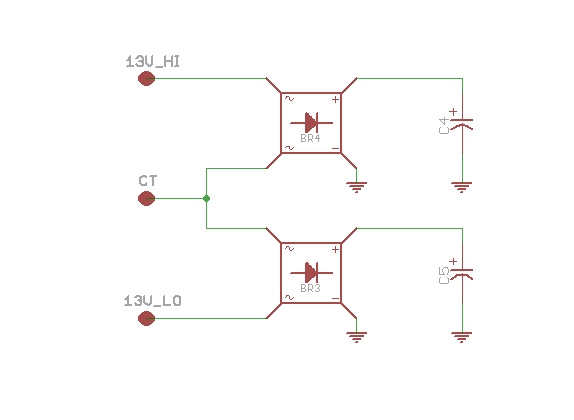
Hello everyone. So basically I was going to construct a circuit which is composed of an opamp precision half wave rectifier (bottom part of schematic) and its power supply (upper part of schematic). The left side of the schematic is a center tapped, 220Vac to 15Vac (both in RMS) 1A transformer. I wanted to integrate both the opamp rectifier and its power supply into one whole circuit and connect them to the ct transformer. The input side of the supply circuit is 15Vac and the output is 12Vdc. The input of the opamp rectifier is 7Vac (I used a 10k potentiometer to decrease the voltage to avoid clipping). I want to get both the 15Vac and the 7Vac from the transformer.

My problem here is that I don't know how to connect all three part of the circuit together WITH proper grounding/current return path. Is putting all three together possible or should I use two separate transformers for the power supply and the opamp circuit for better results?

If anyone has a sample schematic of a circuit with a built in power supply then sharing it to me would be greatly appreciated. Thanks!

- - - Updated - - -

Oops. Neglect the circuit at the right.
 

Attachments

  • eda.png
    eda.png
    151.4 KB · Views: 121
Last edited by a moderator:

Thanks for replying. I'm sure that the connections at the power supply circuit with a full wave rectifier is correct bit I'm not quite confident with the op amp circuit since I need to feed a sinusoidal waveform to it. The way it should be grounded got me confused. How should I separate the ground planes?
 

It sounds as though you want to do this:


0V ground is one end of the secondary. To get a ground-referenced negative supply, add a negative charge-pump voltage doubler.

Edited to add: I find that you don't need to make it a voltage doubler. Just point a single diode in the proper direction.

The supplies are half-wave. It is the simple way to provide a common 0V ground for all supplies. If you want full-wave then you need more complicated circuitry.
 
I was planning on connecting the circuit this way: AD, BF, BG, and CH. Node E is connected to all other ground symbols drawn. I was hoping that the transformer would supply ac voltage to the bridge rectifier to feed the power supply and at the same time give the main circuit a sinusoidal wave which is needed for the opamp circuit. Are these proposed connections valid or did they violate anything?

flow.png
 

It is feasible to block DC component, by putting a capacitor in series. Then dial a potentiometer to select an offset voltage.

Since I like to experiment with simulations, here is an alternate method to use a center-tap transformer for a single supply.


The 10k resistors aren't needed. They are there to make the simulation run smoothly.

and at the same time give the main circuit a sinusoidal wave which is needed for the opamp circuit.

Unfortunately it appears (theoretically) that you do not get a pure sinewave from the ends of the transformer. It's due to the diodes conducting at peaks of the sine cycle.

You might get a better sine shape by omitting the lower diode.

- - - Updated - - -

In addition the capacitor is liable to distort the sine shape. It may be unnecessary in some cases.
 
I think half-wave rectification should be employed on the upper coil of secondary grounding the terminal "B". Rest will remain as usual. Thus you will get clear sinusoidal wave from terminal "B"-"C".
 
Status
Not open for further replies.

Part and Inventory Search

Welcome to EDABoard.com

Sponsor

Back
Top