plaha9
Newbie level 2
Hello!
I will try to make all step by step.

initial data:
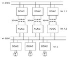
We have a 5 kV grid (+-2.5) and need to convert define power to 700V grid (+-350V).
Power we need in LV grid – 0-40kW (relatively low).
In order to make system reliable, it was a decision to make 3 Dc/Dc (Nr.1.1 and 1.2) isolated converters about 20kW each.
It is beneficial to use the highest frequency of internal AC link as possible to minimize transformers and filters size.
The load of the secondary grid will be power inverters ( Nr. 2) to AC drives.
Problems of concept:
Inverter (Nr1.1)
For every converter in the inverter step we have 5kV voltage and only 20kW power. That means low currents in the semiconductors. If we need a high switching frequency, we can use only IGBT or MOSFET.
There is no IGBT with high voltage and low current on the market. There is no MOSFET with such big voltage/current rate.
So we need to use 3 level inverter or another topology.
Questions:
1. What topology of inverter (Nr 1.1) will be better and what semiconductors to use?
2. If we need to control (Nr.1), can it be controlled only at the primary side (Nr 1.1.) and the secondary side (Nr. 1.2.) make with diodes? Or We need switches on both sides?
3. If the load is Drives connected through the inverters ( Nr.2), this connection should withstand short circuit for some period of time.
So we need short circuit capability of semiconductors in Inverter ( Nr.2). How about short circuit capability in main DC-DC converter ( Nr.1). Is it enough that only rectifier (Nr1.2) will be made of semiconductors which will withstand short circuit or inverter ( Nr1.1) should be also made of such semiconductors?
Thank you!
I will try to make all step by step.

initial data:
We have a 5 kV grid (+-2.5) and need to convert define power to 700V grid (+-350V).
Power we need in LV grid – 0-40kW (relatively low).
In order to make system reliable, it was a decision to make 3 Dc/Dc (Nr.1.1 and 1.2) isolated converters about 20kW each.
It is beneficial to use the highest frequency of internal AC link as possible to minimize transformers and filters size.
The load of the secondary grid will be power inverters ( Nr. 2) to AC drives.
Problems of concept:
Inverter (Nr1.1)
For every converter in the inverter step we have 5kV voltage and only 20kW power. That means low currents in the semiconductors. If we need a high switching frequency, we can use only IGBT or MOSFET.
There is no IGBT with high voltage and low current on the market. There is no MOSFET with such big voltage/current rate.
So we need to use 3 level inverter or another topology.
Questions:
1. What topology of inverter (Nr 1.1) will be better and what semiconductors to use?
2. If we need to control (Nr.1), can it be controlled only at the primary side (Nr 1.1.) and the secondary side (Nr. 1.2.) make with diodes? Or We need switches on both sides?
3. If the load is Drives connected through the inverters ( Nr.2), this connection should withstand short circuit for some period of time.
So we need short circuit capability of semiconductors in Inverter ( Nr.2). How about short circuit capability in main DC-DC converter ( Nr.1). Is it enough that only rectifier (Nr1.2) will be made of semiconductors which will withstand short circuit or inverter ( Nr1.1) should be also made of such semiconductors?
Thank you!