Continue to Site

Welcome to EDAboard.com

Welcome to our site! EDAboard.com is an international Electronics Discussion Forum focused on EDA software, circuits, schematics, books, theory, papers, asic, pld, 8051, DSP, Network, RF, Analog Design, PCB, Service Manuals... and a whole lot more! To participate you need to register. Registration is free. Click here to register now.

problem with analog filter

Status
Not open for further replies.

bogdani1991

Newbie level 4
Joined
Feb 26, 2016
Messages
7
Helped
0
Reputation
0
Reaction score
0
Trophy points
1
Activity points
49
I need to solve the two requirements below:
a) I must calculate Vo
b) R1 to find so behave inductive circuit.
 

Attachments

  • pozz.jpg
    pozz.jpg
    24.2 KB · Views: 51

Hi,

is the source impedance at Vi ideal (= zero), or do you have to calculate with a true source impedance?

Klaus
 

the source impedance at Vi ideal = zero
 

Hi,

then the lower OPAMP, R1, R3 and 2 x "R" is usesless.

Only the upper OPAMP, R3 and C is used.

I hope this makes it more easy now. ;-)

Klaus
 

I need to solve the two requirements below:
a) I must calculate Vo
b) R1 to find so behave inductive circuit.

Two comments:
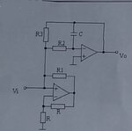
1.) The lower opamp is not useless; it represents - together with the 3 surrounding elements - a Negativ-Impedance-Converter (NIC) which has a negative input resistance at the non-inv. node.
Thus, it can (partly) compensate positive resistors which are connected at this node.

EDIT: This answer applies for a finite source impedance Ri only. Sorry, only now I have recognized that Ri should be zero (ideal voltage source).
bogdani1991 - are you sure about this?

2.) What means "inductive circuit" because - at the same time you are asking for the ouitput voltage? Does it perhaps mean that the input node (where Vin is connected) is required to show inductive behaviour?
 
Last edited:

Hi,

you are correct. The lower OPAMP causes current flow, the same is with R3.

But none of them change any voltage in any node.

(Therefore my answer is correct for voltages, but wrong for currents.)

Klaus
 

An opamp in a "gyrator circuit" simulates an inductor but the schematic in the first post is completely wrong.
Here is a gyrator circuit:
 

Attachments

  • gyrator.png
    gyrator.png
    15.1 KB · Views: 44

Status
Not open for further replies.

Similar threads

Part and Inventory Search

Welcome to EDABoard.com

Sponsor

Back
Top