Continue to Site

Welcome to EDAboard.com

Welcome to our site! EDAboard.com is an international Electronics Discussion Forum focused on EDA software, circuits, schematics, books, theory, papers, asic, pld, 8051, DSP, Network, RF, Analog Design, PCB, Service Manuals... and a whole lot more! To participate you need to register. Registration is free. Click here to register now.

Active Surge Clamp Operation

Status
Not open for further replies.

Storm7

Newbie level 3
Joined
Aug 24, 2016
Messages
3
Helped
0
Reputation
0
Reaction score
0
Trophy points
1
Activity points
26
Hi guys,

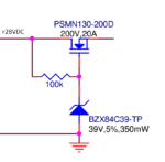
I'm looking for some help in further understanding how this active surge clamp works. The nominal input voltage for the system is 28V and the surge voltage is 80V for 100ms. The output is clamped to ~36V to protect everything downstream.
Clamp.PNG

The Vth of the N-FET is 4V. I've ran some simulations in SIMetrix and I can see that it clamps the surge as desired. I was confused that it didn't show the N-FET conducting during nominal operation...

Any input?

Thanks!
 

Hi,

You have a simulation tool...
Then try to look at V_gs....

Klaus
 

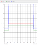
Well I figured it out...auto-axis got the best of me.

Capture.PNG

I saw the output green line at 0 and assumed it was the Y-axis showing 0V :bang:. Well after extending the Y-axis down to 0V, it's much more clear.

Capture2.PNG

Now I'm trying to figure out why there's a ~4V drop across the nfet with its low rds_on.
 

Hi,

V_gs is the voltage between gate and source.
V_gs is not the voltage of the gate wrt GND.

V_gs controls the behaviour of the MOSFET.

Klaus
 

Klaus, I know what V_gs represents. I can subtract the Vs from Vg in the graph I posted above. If you don't have any helpful advice towards my question, can you please refrain from responding to my post in such a condescending manner? Thanks.
 

Hi,

Sorry if you feel I`m condescending, I tried to help, and I tried to point to the answers.

Both your answers will be obvious when you look at a chart with V_gs.

An experienced person maybe sees what happens in the three lines of your chart, but an unexperienced will never see it, because it is not obvious.

But as requested, l´ll be quiet now.

Klaus
 

Not really a clamp per se but a voltage limiter (blocking).
Liable to be pretty crude and the clip level will be very
dependent on the load I-V characteristic (and FET VT
& subthreshold slope variation).
 

Well I figured it out...auto-axis got the best of me.

View attachment 131776

I saw the output green line at 0 and assumed it was the Y-axis showing 0V :bang:. Well after extending the Y-axis down to 0V, it's much more clear.

View attachment 131777

Now I'm trying to figure out why there's a ~4V drop across the nfet with its low rds_on.

The gate and drain are at the same voltage (when it's not clamping) and the gate must be 4V above the source to turn on the fet. So the drain must be 4V above the source too.

This could be reduced with a lower Vgs mosfet. But the bottom line is that this is an incredibly simple circuit and that voltage drop is among the downsides.

I'd consider this a simplistic voltage regulator. You could use an actual voltage regulator IC which would be another easy way to reduce the voltage drop.
 

Status
Not open for further replies.

Similar threads

Part and Inventory Search

Welcome to EDABoard.com

Sponsor

Back
Top