Continue to Site

Welcome to EDAboard.com

Welcome to our site! EDAboard.com is an international Electronics Discussion Forum focused on EDA software, circuits, schematics, books, theory, papers, asic, pld, 8051, DSP, Network, RF, Analog Design, PCB, Service Manuals... and a whole lot more! To participate you need to register. Registration is free. Click here to register now.

[PIC] PIC32MX795F512H mikroC PRO for PIC32 HID bootloader

Status
Not open for further replies.

Alloy

Advanced Member level 4
Joined
Apr 3, 2016
Messages
116
Helped
0
Reputation
0
Reaction score
0
Trophy points
16
Activity points
1,003
Hello guys
There is a ready-to-use bootloader in mikroC PRO for PIC32 for PIC32MX795F512H.
It works with mikroBootloader USB HID.exe.
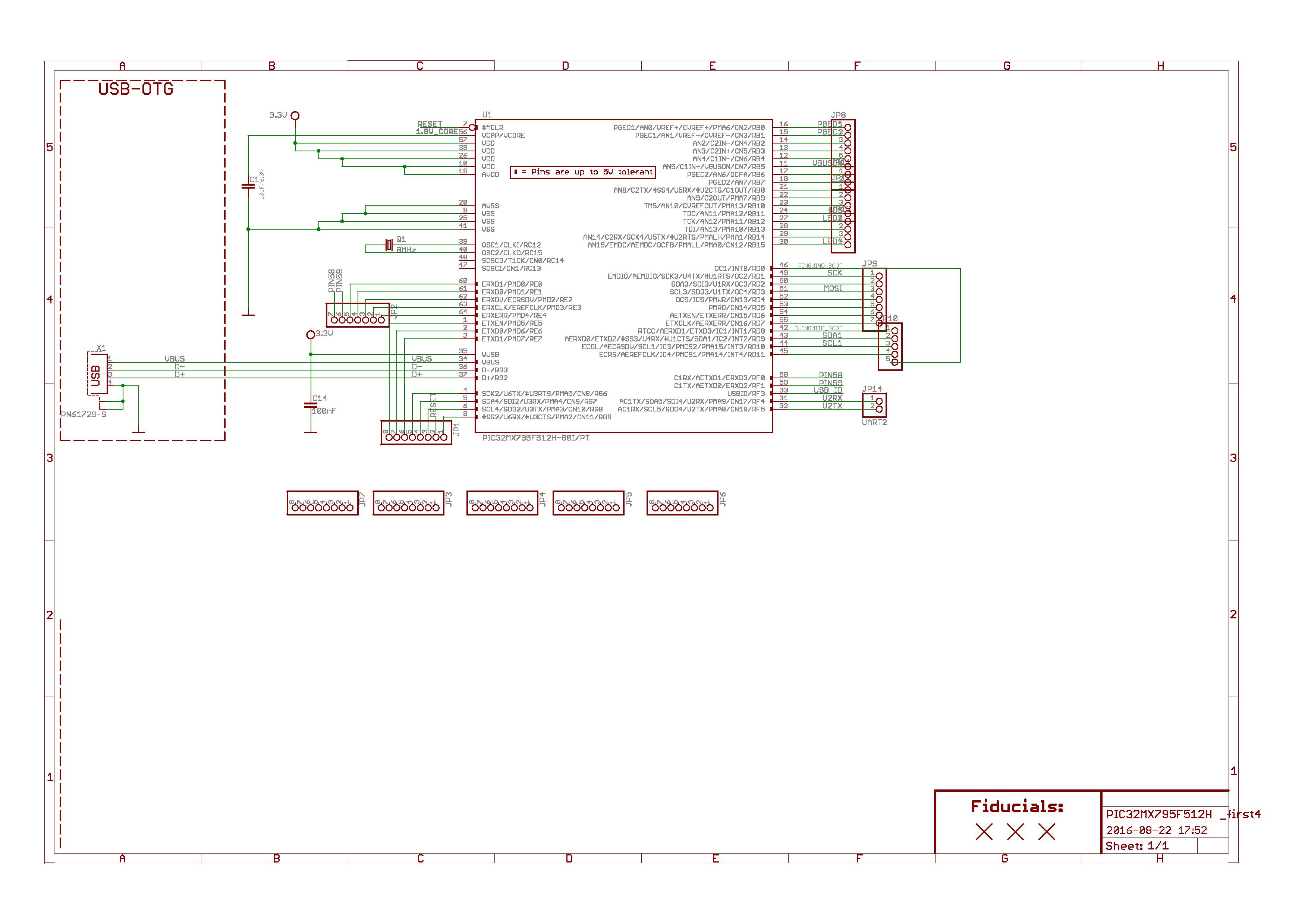
But what are the connection requirements for the PIC? I mean, the simplest schematic to work with bootloader?
Thanks in advance!
 

Check the schematic of mikroMedia Plus for PIC32 for schematic. Just the USB connection.
 

So, to sum things up:
- 5V from USB to VBUS
- VUSB to 3.3V
- all GND and AGND to ground, all VDD and AVDD to 3.3V
- D+ to D+, D- to D- (obviously)
- 8MHz crystal
- MCLR 10k pullup
- VCAP 10uF to ground
Please check the schematic:

What about USB ID pin? Can be left floating in the air?
 

Which post you referred for the circuit ?
 

Both and datasheet, and I've included only components for USB operation. I will add 3.3V regulator as well, and 100nF capacitors, but those are obvious things.
 

I don't know the board so this might not be relevant . The MCUs do not come pre-programmed from Microchip so you need to put the bootloader code into the MCU in the first place, typically via the ICSP interface. Of course, if this has been done for you by someone else then that will be fine.
Susan
 

Use main schematic with power supply schematic from this schematic provided here.

https://www.mikroe.com/mikromedia/plus/pic32mx7/

This isn't really an answer to my question. That power supply schematic contains some chips like TPS2041B, TPS63060 even some MOSFETs like DMP2160UW and diodes like PMEG3010ER. And the battery charger...
I want just the *minimal* connection, so as for the power supply I will just use a single 3.3V LDO with some capacitors.

I don't know the board so this might not be relevant . The MCUs do not come pre-programmed from Microchip so you need to put the bootloader code into the MCU in the first place, typically via the ICSP interface. Of course, if this has been done for you by someone else then that will be fine.
Susan

Hey, I know it very well, the PGD/PGC and RESET pins are on goldpins on my schematic, so what's the problem?
 

What about USB ID pin? Can be left floating in the air?
USBID pin would be used in case you are implementing OTG (dual role) functionality. I guess you don't. I also don't expect that the mikroC HID code will utilize the pin.

This isn't really an answer to my question.
I believe there are no open question at all.
 

Ok, so I assume that the schematic I've posted is correct. I will add more 100nF capacitors, 3.3V LDO and will try to flash bootloader there with PICKIT and then to use it.
 

Status
Not open for further replies.

Part and Inventory Search

Welcome to EDABoard.com

Sponsor

Back
Top