Continue to Site

Welcome to EDAboard.com

Welcome to our site! EDAboard.com is an international Electronics Discussion Forum focused on EDA software, circuits, schematics, books, theory, papers, asic, pld, 8051, DSP, Network, RF, Analog Design, PCB, Service Manuals... and a whole lot more! To participate you need to register. Registration is free. Click here to register now.

Microcontroller based speed control of ac motor

Status
Not open for further replies.

Alexmario

Newbie level 2
Joined
Aug 22, 2016
Messages
2
Helped
0
Reputation
0
Reaction score
0
Trophy points
1
Activity points
20
Hi

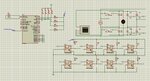
My objective in this project is to control the speed of an ac induction motor by varying the frequency
using SCRs that form the cycloconverter.

Triggering gate pulses for each SCR are generated by the micocontroller as per the code written.

The PROBLEM i have is that the SCRs conduct even with no pulse at their gate. i Need a control circuit for triggering these SCRs.

Here is my proteus design;
 

Attachments

  • FYP.rar
    19.7 KB · Views: 94

Is there a good reason for using a Cycloconverter? That is very old hat these days and does not give particularly good performance with regards to direct Torque control.
 

I didn't see your design but pull up the inputs for SCR triggering pulse from the micro controller pins.Or you can use triac in place of SCR
 

This is actually my end of year project. I'm to design a microcontroller based speed control of ac motor using the CYCLOCONVERER.
 

A cycloconverter is a very interesting project to do with a microcontroller.
I can't open your attachment on my phone. Does it have gate to cathode resistors on each SCR?
They are absolutely necessary.
 

This is the Attachment he told about
 

Attachments

  • Untitled.jpg
    Untitled.jpg
    168.7 KB · Views: 124

The circuit is completely wrong, fortunately you are operating it only in a simulation, otherwise you'll see a lot of smoke.

With transistor opto couplers, you need a separate trigger power supply for each SCR cathode node, four in this case. Trigger transformers are a usual means, also opto triacs (e.g. MOC3020) can work, they need a series rectifier diode to block negative voltages. Or use four triacs instead of SCR pairs.

To mention a possible problem, triggering a cycloconverter wrongly will short the power supply and cause catastrophic failure.

I would never connect a LED without series resistor, even in a pure simulation circuit.
 

Status
Not open for further replies.

Similar threads

Part and Inventory Search

Welcome to EDABoard.com

Sponsor

Back
Top