Continue to Site

Welcome to EDAboard.com

Welcome to our site! EDAboard.com is an international Electronics Discussion Forum focused on EDA software, circuits, schematics, books, theory, papers, asic, pld, 8051, DSP, Network, RF, Analog Design, PCB, Service Manuals... and a whole lot more! To participate you need to register. Registration is free. Click here to register now.

Building a high power, high voltage (565V) DC power supply

Status
Not open for further replies.

Barry675

Newbie level 3
Joined
Aug 19, 2016
Messages
3
Helped
0
Reputation
0
Reaction score
0
Trophy points
1
Activity points
45
Hello,

I need to build a fixed voltage DC power supply to emulate a large lithium-ion battery pack in order to drive an inverter as part of an evaluation test bed.

I would like to rectify 400V 3-phase power and use this to make a fixed 565V DC power supply. I would appreciate any guidance on this. Is it as straightforward as implementing a 3-phase full wave rectifier circuit and then put sufficient capacitance on the output to meet my target ripple voltage? The power rating of the converter needs to be about 10 kW.
I have chosen this idea as it seems to be the simplest solution and will not be excessively expensive (~€1k). Are there better similarly price off the shelf solutions in this range?

I am not familiar with the electrical behaviour of large lithium-ion battery packs but do they display much ripple? Can anyone suggest a target ripple % for rectifier? There's no point in making it have 1% ripple at max load if a battery pack will have 10%.

Can anyone suggest any references or guides on what the best accepted practices for such a device are? What is the state of the art in this area - I see quite a bit about active power factor correction but I'm not sure if this is necessary.

Any advice would be greatly appreciated,

Barry
 

Three phase rectifier with the capacitor the supply method used by most industrial VFD, except for those that use an active PFC rectifier or bidirectional active front end (complex and expensive). Ripple versus capacitance can be estimated by rules of thumb formula or exactly determined in a circuit simulation.

A three phase sine inverter has constant instantaneous power by nature and thus generates no ripple on it's own. Means you have potentially zero DC bus ripple in a battery supplied inverter, a rectifier supply can't cope with it.

DC bus ripple can be compensated in pwm generation so that it doesn't affect the inverter output voltage, but it reduces of course the available undistorted output voltage. A ripple amount of 5 percent seems tolerable for me, up to 10 if necessary.
 

A single 3.7v LiPo cell has an ESR less than 0.1Ω . to provide 20A at 565V choose the A-h capacity you need to determine the number of parallel , series strings at desired current. It might end up looking like a Tesla battery pack or maybe just an array of 157S4P or about 628 X 16850 cells.

This will not be any cheaper to emulate.

You would need at least a 10kVA transformer, or more i.e. give 30% margin.
Then add 10kVA active PFC , 3 phase 100A diodes to give an ESR < 0.01 Ω then low ESR Caps such that ESR*C = 2/f to 5/f to regulate ripple.

total cost is likely to exceed your budget.
 

Assuming you are talking about 400v phase to phase, and 230v phase to neutral supply.

A straight six diode bridge will charge to twice the peak of 230v rms, or in theory about 650 volts dc. You can reduce that by any amount by using three bucking auto transformers.

A much nicer way would be to try and source a second hand three phase variac.
Connect that to a six diode bridge and some serious capacitance.
Then you have a monster 0 to 650v dc power source where you can tweak the output voltage under load to the exact voltage required.
Handy for testing under and over voltage functionality of the inverter too.

These variacs are normally rated for continuous operation in still air. If you submerge one into a tank of oil, the power rating can be safely just about doubled.

Also, because you can wind it up from zero manually, current inrush into your capacitors will not be an issue. Very simple an robust and should come in well under your budget.

I have a three phase 15A variac that I sometimes hook up as a high voltage dc supply, and it works very well,
 
Last edited:

A single 3.7v LiPo cell has an ESR less than 0.1Ω . to provide 20A at 565V choose the A-h capacity you need to determine the number of parallel , series strings at desired current. It might end up looking like a Tesla battery pack or maybe just an array of 157S4P or about 628 X 16850 cells.

This will not be any cheaper to emulate.

You would need at least a 10kVA transformer, or more i.e. give 30% margin.
Then add 10kVA active PFC , 3 phase 100A diodes to give an ESR < 0.01 Ω then low ESR Caps such that ESR*C = 2/f to 5/f to regulate ripple.

total cost is likely to exceed your budget.

Can you explain the need for a transformer? I should have been more explicit in the requirements. 565 VDC is not a hard requirement, I just took that as being the rectified DC voltage for 3-phase 400V power. If it's a small bit above or below that, it will be fine. The inverter can take an input of 200-800 VDC.
 

Assuming you are talking about 400v phase to phase, and 230v phase to neutral supply.

A straight six diode bridge will charge to twice the peak of 230v rms, or in theory about 650 volts dc. You can reduce that by any amount by using three bucking auto transformers.

A much nicer way would be to try and source a second hand three phase variac.
Connect that to a six diode bridge and some serious capacitance.
Then you have a monster 0 to 650v dc power source where you can tweak the output voltage under load to the exact voltage required.
Handy for testing under and over voltage functionality of the inverter too.

These variacs are normally rated for continuous operation in still air. If you submerge one into a tank of oil, the power rating can be safely just about doubled.

Also, because you can wind it up from zero manually, current inrush into your capacitors will not be an issue. Very simple an robust and should come in well under your budget.

I have a three phase 15A variac that I sometimes hook up as a high voltage dc supply, and it works very well,

I like this variac idea. The cost for a 10+ kVa transformer is quite good (under £1000 certainly). Having a high power-high voltage adjustable supply would be very valuable.
 

Check out e-bay from time to time, I purchased mine from a second hand equipment broker. It was a long time ago and I cannot now remember how much I paid, but it was not a lot.
 

A straight six diode bridge will charge to twice the peak of 230v rms, or in theory about 650 volts dc. You can reduce that by any amount by using three bucking auto transformers.

No, peak voltage is sqrt(2)*400 = 565 V. Thus inverters with 3-phase (230/400V) supply are designed for 560V nominal DC bus voltage. A three-phase variac can be nevertheless helpful to test the inverter with reduced voltage and avoid catastrophic failure in case of soft- and hardware faults.
 

a variac can help reduce the starting surge current charging up the caps, but you probably have to create the VAR rating by 30% due to peak pulse current crest factor. >10kVA variac start to get expensive. 5kVA are cheap $200 used.
 

A reference book I have here says the rms transformer current in each phase will be 82% of the final dc output current.

The variac I have is rated 15 amps per phase. Three of those should produce 18.29 theoretical dc amps at any output voltage setting.

If we set 560v dc and 18 amps, that comes out to 10,080 watts.

Still not sure about the actual true theoretical dc output voltage here.
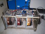
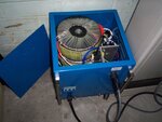
I have such a supply (about 8Kw) running here right now. It uses three large toroidal buck transformers, a six diode bridge, common mode choke and two filter capacitors connected in series, with their centre point wired to mains neutral.

Supply.jpg

Each side charges up these capacitors to the nominal peak voltage (phase to neutral) and there is a +ve output and a -ve output with respect to mains neutral.
Its a difficult thing to measure, because the phase voltages are never the same, and the incoming mains waveform is severely flattened at the top (not all by me !).
The actual dc output has more to do with mains peak voltage than rms in this application, and the flattened waveform reduces the peaks.

If you decide to use a variac, these always have tappings at the high end, so that at the maximum setting you can arrange get slightly higher voltage out than the incoming mains if required, and still get 18 dc amps.

All interesting stuff.

- - - Updated - - -

This is what you need !

variac.jpg
 

Hi,

A straight six diode bridge will charge to twice the peak of 230v rms, or in theory about 650 volts dc. You can reduce that by any amount by using three bucking auto transformers.
This is true when you have two capacitors at the output:
* one from bridge + output to star point
* the other from bridge - to star point
Then the voltage across both capacitors is about 650V

FvM is correct if you have one single capacitor connected between + output and - output of the bridge.

Klaus
 
Thank you for clarifying that Klaus !

This problem has been bugging me for the last day or so. I can see perfectly logical reasons why both answers are correct, but they do not agree.
 
Last edited:

This is true when you have two capacitors at the output:
* one from bridge + output to star point
* the other from bridge - to star point
Then the voltage across both capacitors is about 650V
Do you know any industrial three-phase inverter that connects the star point?
It would bring the serious disadvantage of a 3rd harmonic current component.
 

Three phase motors and transformers are invariably Wye connected for that very reason.

In my application the main dc load is between -ve dc and +ve dc, the neutral is just the mid point reference with little or no residual dc.
Its basically like a non grounded 0v reference if you know what I mean.
It decouples both the dc rails to neutral, mainly for noise reasons.

Without that neutral mid point, both dc lines would be all over the place with noise.

There will definitely be a harmonic current in the neutral, but its not very high. The ripple current through the capacitors being only a couple of percent, especially with a fairly large common mode choke after the rectifier.
 

No doubt that a +/- 325 V supply with N-connected midpoint has some applications. I was just talking about 3-phase inverters state-of-the-art. And as Barry675 is asking for 565V rather than 650V DC, the usual solution seems to fit here as well.
 

Hi,

My post was not meant as a recommendation, it just explains the voltages.

It shows that there is a difference compared to a single phase transformer with center tap.
( where it makes no difference if you use
* one capacitor between bridge rectifier + out and -out
* or you connect two capacitors to the center tap.
On schematic this maybe looks similar than the connection to a star point)

And of course i have to agree that - especially for high power devices - one should avoid the star point connection.

Klaus
 

No doubt that a +/- 325 V supply with N-connected midpoint has some applications. I was just talking about 3-phase inverters state-of-the-art. And as Barry675 is asking for 565V rather than 650V DC, the usual solution seems to fit here as well.
Yes have to agree.

My system is only +/- 220v dc pretty much fixed output, which is why there are the three big toroids.
 

Status
Not open for further replies.

Part and Inventory Search

Welcome to EDABoard.com

Sponsor

Back
Top