Continue to Site

Welcome to EDAboard.com

Welcome to our site! EDAboard.com is an international Electronics Discussion Forum focused on EDA software, circuits, schematics, books, theory, papers, asic, pld, 8051, DSP, Network, RF, Analog Design, PCB, Service Manuals... and a whole lot more! To participate you need to register. Registration is free. Click here to register now.

Spectrum analyzer imput impedance questions

Status
Not open for further replies.

neazoi

Advanced Member level 6
Joined
Jan 5, 2008
Messages
4,119
Helped
13
Reputation
26
Reaction score
15
Trophy points
1,318
Location
Greece
Activity points
36,918
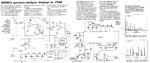
Hello, this spectrum analyzer has a 50R input resistor.
I wonder, why is it needed?
The input filter is designed for 50R but why is the resistor needed?

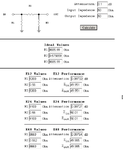
Second question is, I have designed a 50R step attenuator, that will be placed at the input of the spectrum analyzer. Do I need to include the 50R resistor and where?
At the input of the attenuator (input of the analyzer), or at the output of the attenuator, or at both the input and the output of the attenuator?
 

Attachments

  • spectrum analyzer.jpg
    spectrum analyzer.jpg
    286.2 KB · Views: 262

Your step attenuator should be designed for 50 ohms, and it will then correctly terminate the input into 50 ohms, regardless of attenuator setting.

The output of the switched attenuator also needs to be correctly terminated if the db steps of the last stages of the attenuator are to be correct.
Whatever the switched attenuator feeds into needs to be corrected back to 50 ohms.
 
  • Like
Reactions: neazoi

    neazoi

    Points: 2
    Helpful Answer Positive Rating
The 50Ω resistor is probably there to keep the filter happy when a regular scope probe is used. If you are putting a 50Ω step atten on the input, the resistor should NOT be there (it would reduce the input to the filter to 25Ω).
 
  • Like
Reactions: neazoi

    neazoi

    Points: 2
    Helpful Answer Positive Rating
To decide if the 50 ohm termination resistor (or a different value) is required or not, you need to know the mixer input impedance. Do you know it?

I tend to agree with SLK001 that (in lack of a specification) we should assume roughly 50 ohm input impedance and omit the 50 ohm resistor. Better measure the actual input impedance.

My confidence in the posted design is however limited when I see that they didn't even manage to name Minicircuits SBL-1 correctly.
 

The 50Ω resistor is probably there to keep the filter happy when a regular scope probe is used. If you are putting a 50Ω step atten on the input, the resistor should NOT be there (it would reduce the input to the filter to 25Ω).

Thanks.
The step attenuator is composed of 50R steps and the mixer has 50R impedance, as well as the filter.

1. I wonder, if the step attenuator is set to 0db (all switches are bypassed) then the 50R resistor SHOULD be included there, to "keep the filter happy" like you said, shouldn't it? (i.e. to measure higher impedance circuits at 50R)

2. I also have another thought. I believe the resistor is good to be there, but there has to be an option to switch it out.
So for known 50R circuits that need to be tested, it will be switched out, to avoid making measurements on 25 ohms instead.
But for high impedance input circuits, it may be useful to switch it back in, so that one could see how his high impedance circuit will "behave" when terminated to 50 ohms.

What do you think of these two thoughts?
 
Last edited:

Replace the 50Ω resistor with a dedicated 1-dB attenuator (in addition to your step atten). That should keep everything happy. The downside is an extra 1-dB of loss that you will need to account for.
 
  • Like
Reactions: neazoi

    neazoi

    Points: 2
    Helpful Answer Positive Rating
Replace the 50Ω resistor with a dedicated 1-dB attenuator (in addition to your step atten). That should keep everything happy. The downside is an extra 1-dB of loss that you will need to account for.

That's clever, thanks!
Why not using a 0.1dB attenuator instead of a 1dB?
This should reduce the "error" 10 times, and if this 0.1dB error is acceptable (usually the case), there is no need to calculate anything.
It will still present a 50R impedance in/out.

A 0.1dB Pi attenuator is attached.

What do you think?
 

Attachments

  • Untitled.png
    Untitled.png
    17.7 KB · Views: 161

A 0.1dB atten is a little harder to realize than a 1dB. This is all to keep the front end filter happy. Most spectrum analyzers don't have an input filter like this. The designer put it in to keep image problems from showing up in the output. There is a better home build SP that has an input from 0-1000MHz, but is a little more complex (I'm beginning to build this one). There is a Yahoo Group for it at Spectrum Analyzer Projects
 
  • Like
Reactions: neazoi

    neazoi

    Points: 2
    Helpful Answer Positive Rating
As far as I understand, the 1 dB attenuator was intended to achieve at least partial filter matching with unmatched input impedance. But why 0.1 dB? It seems just useless.
 

As far as I understand, the 1 dB attenuator was intended to achieve at least partial filter matching with unmatched input impedance. But why 0.1 dB? It seems just useless.

I am thinking of 0.1db, so that it will still match to 50R, whereas I won't need to compensate for this small error in the measurements. But if it was 1dB it would be a serous error that would need to be compensated.
 

A 1dB error on a SA like this is not likely to even be noticed. You're not expecting to be able to measure to 1dB, are you?

You need to put a 0.1dB atten in front of the filter in a simulator with a 1M across it and examine the response of the filter. The problem with improperly terminated filters is that the whole response starts to collapse. After you simulate the 0.1dB atten, do the same with the 1dB. Find an atten where the response is acceptable. A constant attenuation can be calibrated out.

I thought the filter would be happy if it sees 50R at the input, no matter if there is a 50R 0.1db attenuator or a 50R 1db attenuator. Why does it make a difference since both attenuators are 50R?
 

The terminating effect of 0.1dB attenuator is equivalent to a 5 kOhm parallel resistor = about no termination.
 

The SLB-1 mixer is pretty well matched to 50 ohms. VSWR 1.4:1 max. So adding another 50 ohm resistor at the input connector...is kind of like wishing for a 25 ohm input impedance! I would leave it off.

I actually would prefer what others have recommended, adding a pad at the input instead. That way even if the mixer is mismatched, the effective return loss at the spectrum analyzer input would be improved, which is important if you are trying to make an accurate power reading. With a bad input impedance, and any cable length, you will get some ripple in the power measurement. I would go for at least a 3 dB pad.
 
  • Like
Reactions: neazoi and FvM

    FvM

    Points: 2
    Helpful Answer Positive Rating

    neazoi

    Points: 2
    Helpful Answer Positive Rating
The SLB-1 mixer is pretty well matched to 50 ohms. VSWR 1.4:1 max. So adding another 50 ohm resistor at the input connector...is kind of like wishing for a 25 ohm input impedance! I would leave it off.

I actually would prefer what others have recommended, adding a pad at the input instead. That way even if the mixer is mismatched, the effective return loss at the spectrum analyzer input would be improved, which is important if you are trying to make an accurate power reading. With a bad input impedance, and any cable length, you will get some ripple in the power measurement. I would go for at least a 3 dB pad.

What is a good value for the isolator, so that it allows for good matching and isolation but without too much lost of the input signal?
You mention 3db, but is this enough for this SA design?

Also, I am thinking of using power resistors ~1-2W for this input attenuator. Is that true that if I use say 2W resistors the power input to the analyzer can be up to 2W, or it does only depend on the attenuation value, or both?
I am asking because one way to measure higher power sources on the scope is to shunt the 1M input with a power 50R resistor, but the analyzer has already a 50R input, so a single shunt resistor is no good.
 

Also, I am thinking of using power resistors ~1-2W for this input attenuator. Is that true that if I use say 2W resistors the power input to the analyzer can be up to 2W, or it does only depend on the attenuation value, or both?

No, it's not true. If you build a 3dB pad with 2W resistors and input 2W, 1 watt of power would emerge from the output. This is too much power to input to your mixer, which has a max input of 50mW. If you need to input large amounts of power, get some power attenuators to drop the power to the input of your SQ.
 

No, it's not true. If you build a 3dB pad with 2W resistors and input 2W, 1 watt of power would emerge from the output. This is too much power to input to your mixer, which has a max input of 50mW. If you need to input large amounts of power, get some power attenuators to drop the power to the input of your SQ.

Thanks. And what is a good value for the isolator, so that it allows for good matching and isolation but without too much lost of the input signal? 3db, 6db, ...
 

Thanks. And what is a good value for the isolator, so that it allows for good matching and isolation but without too much lost of the input signal? 3db, 6db, ...

First you have to answer what is your intended use for your SA?
 

First you have to answer what is your intended use for your SA?

Measuring signals amplitudes on HF and their harmonics amplitudes. This is the main purpose. I do not think it's oscillators will be too stable to measure sidebands of an SSB signal (together with the use of narrower IF filters). Maybe if ovenizing the oscillators would help?
 

How a SA is usually used, is selecting an appropriate attenuator to knock the power down to a level that is safe for the input of the SA. In your case, it is < 50mW... I would stay < 20mW. If I was interested in viewing a 2W transmitter's output and harmonics, I would use a 20dB pad with at least a 5 watt rating.

As for viewing a SSB signal, the stability of the oscillator is adquate for that task. It probably isn't good enough to be able to measure frequency precisely, but for most everything else it should be okay. I see no need to ovenize the oscillator. Anyway, ovenizing the oscillator isn't as stright forward as it seems.

As for your input, I would drop the filter (and the 50Ω resistor) and replace them with a 1-dB pad. The pad will help improve the match between the input and the mixer. It is easily calibrated out, so there will not be much of an impact on measurements. It is the engineer's responsibility to know the limitations of his equipment and how to compensate his measurements to account for those limitations. For instance, if you are looking to measure the output of a 90MHz transmitter and its harmonics, you will know that the 2nd harmonic on will be OUTSIDE of your equipments capability, so you will have to take steps to filter out those harmonics prior to the input to your SA. If you don't, you will see image products IN YOUR PASSBAND that will try to confuse you.
 
  • Like
Reactions: neazoi

    neazoi

    Points: 2
    Helpful Answer Positive Rating
Status
Not open for further replies.

Part and Inventory Search

Welcome to EDABoard.com

Sponsor

Back
Top