libyantiger
Member level 5
i fixed many of those Chinese commercial Chinese 12vdc to 220ac inverters i know that
the lm324 compactor is the one responsible for all sorts of protections in these units
a 5vdc output from the compartor due to any sort of fault...like lvp ovp ocp etc etc
the 5vdc will go to the 4th pin in the tl494 this pin will shutdown the tl494 if logic high
reach it and once the tl494 goes down the entire inverter will shutdown...
ofcourse i am talking about tl494 in the primary side that is responsible to turn the 12vdc to
250vdc not the the tl 494 at the secondery which is gonna turn the 250 vdc into 220vac
when we look at it ..it is easy for lm324 to detect a low voltage case ...just a voltage
divider on the 12vdc bus and the mission is done
over voltage also can be easily detected with the same method "voltage divider"
however i cant see the notorious current sense resistor in any of the primary fets ...those
resistor ARE easily noticed in any uc38xx based smps used for current sensing and thus
over current can be calculated ....but in these inverters i can not see any
way for the tl494 or the lm324 for measuring an over current state??????????
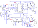
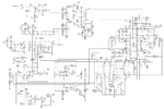
i posted an inverter schismatic for discussion and ideas
- - - Updated - - -
ok here is the image

