Continue to Site

Welcome to EDAboard.com

Welcome to our site! EDAboard.com is an international Electronics Discussion Forum focused on EDA software, circuits, schematics, books, theory, papers, asic, pld, 8051, DSP, Network, RF, Analog Design, PCB, Service Manuals... and a whole lot more! To participate you need to register. Registration is free. Click here to register now.

[SOLVED] PIC16F628A - Simple timer digit error

Status
Not open for further replies.

Ragnar22

Member level 1
Joined
Aug 5, 2016
Messages
36
Helped
1
Reputation
2
Reaction score
1
Trophy points
8
Location
Lisbon
Activity points
267
Hi guys!! ( this is my first post here )
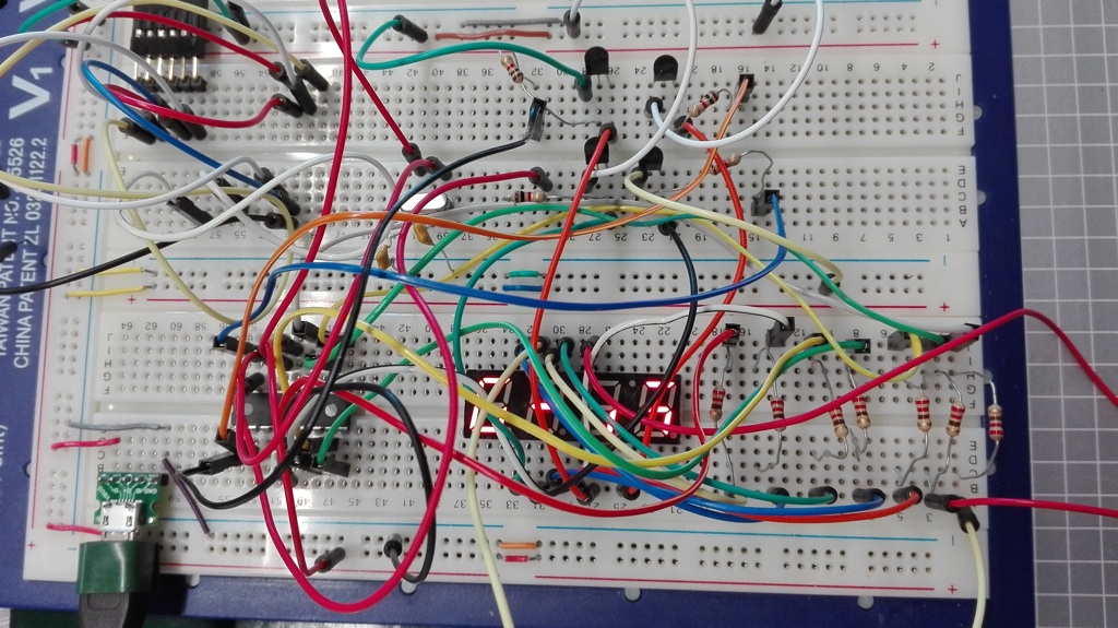
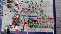
Before I start I have to say that I am new at programming PIC MCU and I am really annoyed with something, at multiplexing a theorically simple 4 digits 7seg display (common anode) when I simulate in ISIS PROTEUS it goes and runs perfectly but when I put it in breadboard testing the digits are all messed up like the photo demonstrates. Anyone knows wich are the common causes for this type of error?
NOTE: most important comments are in english but some are in portuguese so dont mind those


Code:
        // ---  Hardware ---
#define digito_minutos1 RA3_bit 
#define digito_minutos2 RA2_bit
#define digito_horas1 RA1_bit
#define digito_horas2 RA0_bit


int display(int num);                          //Exibe o valor correspondente no display de catodo comum


// --- Variávei Globais ---
int tempo  = 0x00;                           //Inicializa contador
int control = 1;                           //Variável de controle (para saber qual display está ativo)
int segundos, minutos1,horas1,minutos2,horas2 = 0;


// --- Rotina de Interrupção ---
void interrupt()
{
     if(T0IF_bit)                            //Houve o estouro do TMR0?
     {
        T0IF_bit = 0x00;                     //Sim, limpa a flag
        TMR0= 6;
        tempo++;


             if(/*digito_horas2 &&*/ control==1){
                              control = 2;
                              digito_minutos2 = 1 ;
                              digito_horas1   = 1 ;
                              digito_minutos1    = 1;
                              PORTB   = 0b11111111;                    //LIMPA PORTB

                              digito_horas2  = 0;
                              PORTB  = display(horas2);


              }else if(/*digito_horas1 &&*/ control==2){


                    control = 3;
                    digito_minutos2 = 1;
                    digito_minutos1   = 1 ;
                    digito_horas2    = 1;
                    PORTB   = 0b11111111;                   //LIMPA PORTB

                    digito_horas1 = 0;
                    PORTB  = display(horas1);

                    }else if(/*digito_minutos2 &&*/ control==3){


                          control = 4;
                          digito_minutos1 = 1 ;
                          digito_horas1   = 1 ;
                          digito_horas2    = 1;
                          PORTB   = 0b11111111;                    //LIMPA PORTB

                          digito_minutos2 =  0;
                          PORTB  = display(minutos2);

                          }else if(/*digito_minutos1 &&*/ control == 4){

                                control = 1;
                                digito_minutos2 = 1 ;
                                digito_horas1   = 1 ;
                                digito_horas2    = 1;
                                PORTB   = 0b11111111;                   //LIMPA PORTB

                                digito_minutos1 = 0;
                                PORTB  = display(minutos1);
        }

     } //end if (teste de estouro)

} //end interrupt


// --- Função Principal ---
void main()
{

                                         //Desabilita os resistores de pull-up internos
       OPTION_REG = 0x81;                 // e  configura o prescaler para 1:16 ou 1:4 se 11 ou 01 associado ao TMR0
       GIE_bit    = 0x01;                //Habilita a interrupção global
       PEIE_bit   = 0x01;                //Habilita a interrupção por periféricos
       T0IE_bit   = 0x01;                //Habilita a interrupção por estoiro do TMR0

       TMR0       = 0x06;                //Inicia neste valor para dar contagem precisa (250*4*1 us cada estoiro ou seja 1 ms cada estoiro do Timer0)*/


       CMCON = 0x07;      // desabilita os comparadores
       TRISA=0b00000000; //PORTA é configurado como saidas
       TRISB=0b00000000; //PORTB configurado como saídas


       digito_minutos2 = 1 ; // gate signal to pnp transistors to control the displays
       digito_horas1   = 1 ;
       digito_minutos1 = 1 ;
       digito_horas2   = 1 ;

// -- Loop infinito --
     while(1)
     {
        if(tempo == 1000)  // ( 1us(=ciclo maquina) * 4(=PRESCALER) * 250(=256-6)) * 1000 = 1s
       {
          segundos++;  // increments 1 second
          tempo = 0x00;

       }

      if(segundos == 60)
       {

          minutos1++; // increments  minute 1st digit
          segundos = 0;
       }

        if(minutos1 == 10)
       {

          minutos2++; // increments minutes 2nd digit
          minutos1 = 0;
       }
        if(minutos2 == 6)
       {

          horas1++; // increments hours 1st digit
          minutos2 = 0;
       }
        if(horas1 == 10)
       {

          horas2++; // increments hours 2nd digit
          horas1 = 0;
       }


     } //end while

} //end main


int display(int num)
{
    int anode;                               //armazena código BCD

// -- Vetor para o código BCD --
    int SEGMENTO[10] = {0b01000000,0b01111001,0b00100100,0b00110000,0b00011001,0b00010010,0b00000010,0b01111000,0b00000000,0b00011000}    ;

    anode = SEGMENTO[num];                   
    return(anode);                           

} //end display
 

Attachments

  • Circuito.jpg
    Circuito.jpg
    68.1 KB · Views: 158
Last edited by a moderator:

I could not see any explicit delay between consecutive accesses to PORTB, so that considering that your circuit is assembled on a breadboard with so aerial wires, you are certainly facing to signal integrity issues. Try adding a delay before each port assignement of let's say 10ms, gradually decreasing it.
 

I could not see any explicit delay between consecutive accesses to PORTB, so that considering that your circuit is assembled on a breadboard with so aerial wires, you are certainly facing to signal integrity issues. Try adding a delay before each port assignement of let's say 10ms, gradually decreasing it.

Thanks for the tip, I tried putting delay before the PORTB assignements but it stayed the same, only difference is that at some point the frequency of the display leds was possible to be seen.

Note: I tried from 10 ms to 0.5 ms

Code:
void interrupt()
{
     if(T0IF_bit)                            //Houve o estouro do TMR0?
     {
        T0IF_bit = 0x00;                     //Sim, limpa a flag
        TMR0= 6;
        tempo++;


             if(digito_horas2 && control==1){
                              control = 2;
                              digito_minutos2 = 1 ;
                              digito_horas1   = 1 ;
                              digito_minutos1    = 1;

                              PORTB   = 0b11111111;                    //LIMPA PORTB

                              digito_horas2  = 0;
                              [COLOR="#FF0000"]delay_us(500);[/COLOR]
                              PORTB  = display(horas2);


              }else if(digito_horas1 && control==2){


                    control = 3;
                    digito_minutos2 = 1;
                    digito_minutos1   = 1 ;
                    digito_horas2    = 1;

                    PORTB   = 0b11111111;                   //LIMPA PORTB

                    digito_horas1 = 0;
                    [COLOR="#FF0000"]delay_us(500);[/COLOR]
                    PORTB  = display(horas1);


                    }else if(digito_minutos2 && control==3){


                          control = 4;
                          digito_minutos1 = 1 ;
                          digito_horas1   = 1 ;
                          digito_horas2    = 1;

                          PORTB   = 0b11111111;                    //LIMPA PORTB

                          digito_minutos2 =  0;
                         [COLOR="#FF0000"]delay_us(500);[/COLOR]
                          PORTB  = display(minutos2);


                          }else if(digito_minutos1 && control == 4){

                                control = 1;
                                digito_minutos2 = 1 ;
                                digito_horas1   = 1 ;
                                digito_horas2    = 1;

                                PORTB   = 0b11111111;                   //LIMPA PORTB

                                digito_minutos1 = 0;
                                [COLOR="#FF0000"]delay_us(500);[/COLOR]
                                PORTB  = display(minutos1);

        }

     } //end if (teste de estouro)

} //end interrupt
 

Add another delay 1 line above just before each digito_minutos1,2=0 and digito_horas1,2=0 assignments, because the 4 transistors are also subjected to the same issue.

Tip: You can add a constant parameter on code by #define preprocessor, so that further changes for each test will be made just once, instead of in line as you did.
 
I tried several times with different values and these where the results:


Code:
void interrupt()
{
     if(T0IF_bit)                            //Houve o estouro do TMR0?
     {
        T0IF_bit = 0x00;                     //Sim, limpa a flag
        TMR0= 6;
        tempo++;


             if(digito_horas2 && control==1){
                              control = 2;
                              digito_minutos2 = 1 ;
                              digito_horas1   = 1 ;
                              digito_minutos1    = 1;

                              PORTB   = 0b11111111;                    //LIMPA PORTB
                              
                              [COLOR="#FF0000"]delay_us(atraso1);[/COLOR]
                              digito_horas2  = 0;

                              [COLOR="#FF0000"]delay_us(atraso2);[/COLOR]
                              PORTB  = display(horas2);
                              [COLOR="#FF0000"]delay_us(atraso3);[/COLOR]

              }else if(digito_horas1 && control==2){


                    control = 3;
                    digito_minutos2 = 1;
                    digito_minutos1   = 1 ;
                    digito_horas2    = 1;

                    PORTB   = 0b11111111;                   //LIMPA PORTB
                    
                    [COLOR="#FF0000"]delay_us(atraso1);[/COLOR]
                    digito_horas1 = 0;
                    
                    [COLOR="#FF0000"]delay_us(atraso2);[/COLOR]
                    PORTB  = display(horas1);
                    [COLOR="#FF0000"]delay_us(atraso3);[/COLOR]

                    }else if(digito_minutos2 && control==3){


                          control = 4;
                          digito_minutos1 = 1 ;
                          digito_horas1   = 1 ;
                          digito_horas2    = 1;

                          PORTB   = 0b11111111;                    //LIMPA PORTB
                          
                          [COLOR="#FF0000"]delay_us(atraso1);[/COLOR]
                          digito_minutos2 =  0;
                          
                          [COLOR="#FF0000"]delay_us(atraso2);[/COLOR]
                          PORTB  = display(minutos2);
                          [COLOR="#FF0000"]delay_us(atraso3);[/COLOR]

                          }else if(digito_minutos1 && control == 4){

                                control = 1;
                                digito_minutos2 = 1 ;
                                digito_horas1   = 1 ;
                                digito_horas2    = 1;

                                PORTB   = 0b11111111;                   //LIMPA PORTB
                                
                                [COLOR="#FF0000"]delay_us(atraso1);[/COLOR]
                                digito_minutos1 = 0;
                                
                                [COLOR="#FF0000"]delay_us(atraso2);[/COLOR]
                                PORTB  = display(minutos1);
                                [COLOR="#FF0000"]delay_us(atraso3);
[/COLOR]
        }

     } //end if (teste de estouro)

} //end interrupt


NOTE: atraso1 atraso2 atraso3 [ms]

0 0 6 :
0 0 6 ms.jpg
1 0.1 4:
1 01 4  ms.jpg
1 1 0 :
1 1 0 ms.jpg
1 1 3:
1 1 3 ms (1).jpg
1 1 1:
1ms todos.jpg
2 2 0:
2 2 0 ms.jpg
2 2 6:
2 2 6 ms.jpg
0.5 0.5 0
05 05 0.jpg
 

Adding inter-digit delays inside the ISR is not a good idea.

I would suggest the better solution is to multiplex the digits (sequence the RA pins) using the timer interrupt at say 100 times per second and at the same time decrement a counter variable from 100 to zero. When the counter reaches zero the second has elapsed and you re-load the counter then do the clock functions. It will keep time better than using delays inside the ISR and also better maintain the digit brightness because the multiplexing is at a constant rate.

Brian.
 
Regardless from being unsuited to add routines within isr vectors as Brian said above, you did not inserted a delay in the range of milliseconds, but in the range of microseconds, which in the above assemblage I'm not sure if would display a significant difference.
 

I converted ms to us. 1ms = 1000us and so on.

- - - Updated - - -

Hmm I see, I tried to do what u said.
I changed the time that the timer0 takes to "explode" from 10 ms to 2 ms by changing the prescaler and the initialization of the TMR0 but the digits stayed as the image shows:

Capturar.PNG

P.S - thanks for the patiente guys
 

I suspect that your problem is what is known as the "read-modify-write" problem and is caused by making changes to the individual PORT pins too rapidly.
Unfortunately the chip you are using does not have LAT registers that Microchip added to newer devices to get around exactly this problem.
Look at the internet for a technical description of the RMW problem but the solution in your case is to change all of the bits on PORTA at the same time. Looking at your code, you seem to always be setting the various PORTA bits in consecutive instructions. Use a 'shadow' register if you need to set individual bits at different times or work out the correct settings for all of the PORTA pins and write them all at once with one instruction.
Susan
 
I have made a two digits 7segment display with PIC16F628A and two transistors in the past and it worked well.
Are you sure that you have correct segments connected to correct pins?
Maybe try to comment out your code and start with testing if the correct segments are lit?
And then start testing without multiplexing, just display the same digit on all digit displays.
And then add multiplexing.
 

Try:
#define digito_minutos1 PORTA=0x08
#define digito_minutos2 PORTA=0x04
#define digito_horas1 PORTA=0x02
#define digito_horas2 PORTA=0x01

then use the defined name to select the digit. It should write all the bits to PORTA at once and avoid RMW problems. It looks like MikroC code which I can't check at the moment and I do not have ISIS at all.

Brian.
 

I have made a two digits 7segment display with PIC16F628A and two transistors in the past and it worked well.
Are you sure that you have correct segments connected to correct pins?
Maybe try to comment out your code and start with testing if the correct segments are lit?
And then start testing without multiplexing, just display the same digit on all digit displays.
And then add multiplexing.

I did that and the display went fine. Thanks for advise anyway :)
 

I suspect that your problem is what is known as the "read-modify-write" problem and is caused by making changes to the individual PORT pins too rapidly.
Unfortunately the chip you are using does not have LAT registers that Microchip added to newer devices to get around exactly this problem.
Look at the internet for a technical description of the RMW problem but the solution in your case is to change all of the bits on PORTA at the same time. Looking at your code, you seem to always be setting the various PORTA bits in consecutive instructions. Use a 'shadow' register if you need to set individual bits at different times or work out the correct settings for all of the PORTA pins and write them all at once with one instruction.
Susan

Something like this? How do I assign 0 in the same instruction in this case? could u exemplify in this case? thanks in advance

Code:
 if(digito_horas2 && control==1){
                              
control = 2;
                              digito_minutos1, digito_horas1,digito_minutos2 = 1 ;


                              PORTB   = 0b11111111;                    //LIMPA PORTB
                              

                              digito_horas2  = 0; // [COLOR="#FF0000"]????[/COLOR]


                              PORTB  = display(horas2);


              }else if (...)
 

Try:
#define digito_minutos1 PORTA=0x08
#define digito_minutos2 PORTA=0x04
#define digito_horas1 PORTA=0x02
#define digito_horas2 PORTA=0x01

then use the defined name to select the digit. It should write all the bits to PORTA at once and avoid RMW problems. It looks like MikroC code which I can't check at the moment and I do not have ISIS at all.

Brian.

Sry Brian but I didnt understand, my define is basically the same right?

Code:
#define digito_minutos1 RA3_bit
#define digito_minutos2 RA2_bit
#define digito_horas1 RA1_bit
#define digito_horas2 RA0_bit

- - - Updated - - -

I tried this to deal with RMW problem but it didnt work also... :-(


Code:
 if(digito_horas2 && control==1){
                             

                              control = 2;
                              
                            
                              digito_minutos1  = 1; 
                              digito_horas1 = 1   ;
                              digito_minutos2 = 1 ;
                              
                              while(digito_horas1 != 1 || digito_minutos2 != 1 || digito_minutos1 != 1){

                              }

                             PORTB   = 0b11111111;                   //CLEAN PORTB
                              

                              digito_horas2  = 0;
                              while(digito_horas2!=0){
                              
                              }

                              PORTB  = display(horas2);


              }else if   (........)
 

I did better wiring on the circuit. Here's the result: (It gets easier to see with this config)

New Circuit.PNG
 

Sry Brian but I didnt understand, my define is basically the same right?

No, it is quite different. A "#define" does not itself produce code, it just tells the compiler that when it sees the first name, it should substitute anything after it until the end of the line. So when you use "digito_minutos1" the compiler changes it to "RA3_bit". There are other things you can do with #define but in your code it is only there to make it easier to read. Using "digito_minutos1 = 1;" converts to "RA3_bit = 1" and ONLY makes RA3 go to logic high.

My suggestion does more than that because it also changes the other bits in PORTA at the same time. The hexadecimal numbers I used in binary are 1000, 0100, 0010 and 0001, they are loaded into RA3, RA2,RA1 and RA0 when you use one of the defines. It saves you having to make the other bits =0 and loads all the RA pins at the same time.

Brian.
 
Hmm thanks for the explanation Brian but in my case it should be like this right:

Code:
#define digito_minutos1 PORTA = 0b00000111
#define digito_minutos2 PORTA = 0b00001011
#define digito_horas1 PORTA = 0b00001101
#define digito_horas2 PORTA = 0b00001110

- - - Updated - - -

Guys I am ashamed to say that the solution for this was just a bad atribution of the initial variables, In college I remember doing that kind of atribution everyday.... but anyways 1000 thanks to everybody who dedicated time in trying to help me.

Code:
[B][COLOR="#FF0000"]int segundos, minutos1,horas1,minutos2,horas2 = 0;[/COLOR][/B]
 
Last edited:

I know you say this is solved but for anyone coming to this thread in the future, the way to correctly solve the RMW probelm is basically what Betwixt suggested.
Instead of
Code:
// The 'if' statement above this ensures that digit0_horas2 (RA0) is 1
digito_minutos1 = 1; // Port RA3
digito_horas1 = 1;    // Port RA1
digito_minutos2 = 1; // Port RA2
...
digit0_horas2 = 0;    // Port RA0
you should use something like
Code:
PORTA = 0b1110;  // RA3, RA2 and RA1 = 1, RA0 = 0
or to use the definitions that Betwixt defined above
Code:
PORTA = digito_minutos1 | digito_minutos2 | digito_horas1;
This will set all of the PORTA bits at the same time. It also has the important characteristic of NOT requiring the hardware to read the existing state of the PORTA bits (the 'read' part of the problem name) before updating the specified bit ('modify') and then writing all of the bits back to the PORTA register( 'write').
Susan
 

This will set all of the PORTA bits at the same time.
An additional gain on that approach is that the code becomes more portable to other cores which do not supports bit mapping the ports.
 

Status
Not open for further replies.

Similar threads

Part and Inventory Search

Welcome to EDABoard.com

Sponsor

Back
Top