satiz
Member level 5
Hi All,
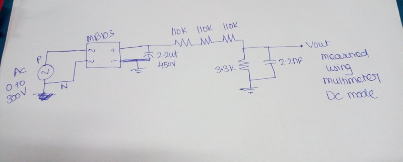
I am planning to measure the AC RMS using microcontroller. Because of size constrain I don't want to use step down transformer. By using bridge rectifier the input AC voltage is converted into DC, then using voltage divider network the rectifier volt is reduced and out put of the voltage divider is filtered and given to microcontroller ADC.
Issue:
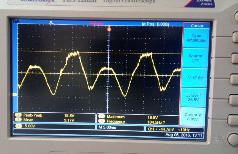
After the bridge rectifier I am not getting the proper rectified output.
The actual output is attached below.

Rectifier part number: MB10s
Voltage divider values : High side 110K 4 numbers. low side 3.3K
Capacitor : 1UF/63 volts
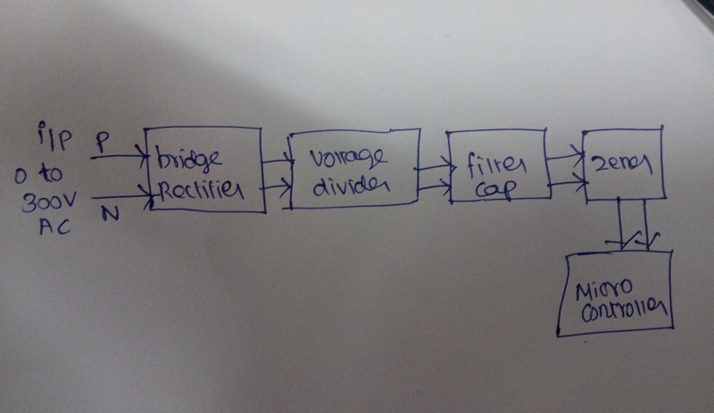
Block diagram:
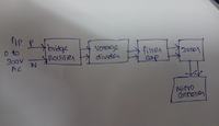
I am planning to measure the AC RMS using microcontroller. Because of size constrain I don't want to use step down transformer. By using bridge rectifier the input AC voltage is converted into DC, then using voltage divider network the rectifier volt is reduced and out put of the voltage divider is filtered and given to microcontroller ADC.
Issue:
After the bridge rectifier I am not getting the proper rectified output.
The actual output is attached below.
Rectifier part number: MB10s
Voltage divider values : High side 110K 4 numbers. low side 3.3K
Capacitor : 1UF/63 volts
Block diagram:
Last edited by a moderator: