Continue to Site

Welcome to EDAboard.com

Welcome to our site! EDAboard.com is an international Electronics Discussion Forum focused on EDA software, circuits, schematics, books, theory, papers, asic, pld, 8051, DSP, Network, RF, Analog Design, PCB, Service Manuals... and a whole lot more! To participate you need to register. Registration is free. Click here to register now.

DC-DC step-up converter efficiency

Status
Not open for further replies.

areebaa

Member level 2
Joined
Oct 20, 2015
Messages
52
Helped
0
Reputation
0
Reaction score
0
Trophy points
6
Activity points
383
hi,

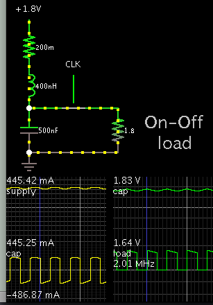
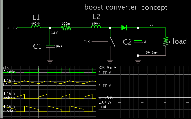
I have designed a simple low power boost converter. vin 1.8V vout 2v fsw=2M .
how can I calculate efficiency with error tolerance ? any help will be appreciated

thanks
 

Hi,

efficiency = P_out / P_in = U_Out * I_out / (U_in * I_in)

What do you mean with "with error tolerance"?

Klaus
 

I mean measuring efficiency, addressed with error tolerance.
in case of low power dc-dc boost converters like if the vin =1.8, vo=2v , L=900nH , fsw=4Mhz , the measuring efficiency can be varying , So, how we can calculate that efficiency with error tolerance.
or a graph w.r.t output current.
secondly, can we estimate the Iin as IL(avg) in case of boost converter or should it be different ? if I consider the IL(avg) as Iin the efficiency calculated becomes very low. how I can estimate the input current.
thanks
 

For low power devices efficiency is not imporatant. Also, it greatly depends from load current.
Basicaly, you will loose power on switching transistor, rectifier and coil. For maximum load you can get 50% duty cycle and perform calculation like this:
Transistor static losses = Ii * Ii * R * Duty cycle
Rectifier losses = Vf * Io * Duty cycle
Coil losses = Rc * Io * Io * Duty cycle
Something like that...
 
Hi,

So, how we can calculate that efficiency with error tolerance.
I still don´t get what you mean with error tolerance...

or a graph w.r.t output current.
For a graph you need a numper of measurement points.
For each value of output current you get a value of input current.
Calculate efficiency as before and automatically you get the points for your graph...

secondly, can we estimate the Iin as IL(avg) in case of boost converter or should it be different ?
For a DC input voltage you should calculate with AVERAGE input current.

how I can estimate the input current.
You must not "estimate" the input current, you should "measure" the input current.
Again: for each single point of your chart.

It´s quite normal that the efficiency is low with low output currents (low output power)
****

I recommend to read datasheets of switching regulator ICs or SMPS to see how they made the efficiency chart.

Klaus
 

Klaus;
what I believe the OP is asking for, is what is the expected efficiency range for datasheet purposes.

An example you can find on the web: Efficiency; 90% typical, 87% minimum @ full load and 1.8 volt input

areebaa:
there is no substitute for actual laboratory measurements, made with good test equipment.
You will require a good number of units, about 25 pieces, measure them and using statistics calculate the average and standard deviation.

Taking many measurements of many units by hand is a long and tedious work. This is where automated test equipment really makes life easier.
 

if for example in my case inductor current fluctuates from 760mA to 850mA , so the average will be (760m+850m)/2 =0.8
in this way if calculate efficiency comes out to very low Eff = 2x 70m / 1.8 x 0.8 = 9.66%
but if we use losses formula efficiency comes to be different: (Pin - Pc - Ps )/pin
 
Last edited:

Hi,

now you use inductor current.... But you should use average_input_current.

I don´t see the circuit, so I can´t decide if using the inductor current makes sense at all.

--> use input current.
Why?

an inductor is a storage device. It can store energy. In general W = I * I * L / 2
But who says that ALL of the stored energy is given to the output with every pulse?

1)
Maybe the current travels from 760mA to 850mA and back.
Then the max. stored energy is 0.85A * 0.85mA * L / 2 and the min stored energy is 0.76A * 0.76mA * L / 2.. therefore the max "transmitted energy" is the difference of both energies.
And this energy has nothing to do with the average_current of the inductance.

2)
Now this difference energy maybe is not 100% fed to the output side... maybe during switching / or maybe during dead_time of an half bridge a part of the energy is stored BACK to the input side (capacitor).
If so, then this causes a short pulse of negative current flow in the input side. This current is increasing the RMS current, but decreasing the average current.
And with decreasing average current there will be decreasing input power.

***********
Again: measure
* input_average_current
* input_average_voltage
* output_average_current
* and output_average_voltage
...
calculate P_in and P_out and calculate efficiency.

Do this with a lot of different load_currents (= output_average_current) and draw your chart.

Klaus
 
in case of boost converter what I think is IL average is equal to input current. please correct me if I am wrong thanks . please see the attached diagram
synboost.png

- - - Updated - - -

in case of boost converter what I think is IL average is equal to input current. please correct me if I am wrong thanks . please see the attached diagram

Hi,

now you use inductor current.... But you should use average_input_current.

I don´t see the circuit, so I can´t decide if using the inductor current makes sense at all.

--> use input current.
Why?

an inductor is a storage device. It can store energy. In general W = I * I * L / 2
But who says that ALL of the stored energy is given to the output with every pulse?

1)
Maybe the current travels from 760mA to 850mA and back.
Then the max. stored energy is 0.85A * 0.85mA * L / 2 and the min stored energy is 0.76A * 0.76mA * L / 2.. therefore the max "transmitted energy" is the difference of both energies.
And this energy has nothing to do with the average_current of the inductance.

2)
Now this difference energy maybe is not 100% fed to the output side... maybe during switching / or maybe during dead_time of an half bridge a part of the energy is stored BACK to the input side (capacitor).
If so, then this causes a short pulse of negative current flow in the input side. This current is increasing the RMS current, but decreasing the average current.
And with decreasing average current there will be decreasing input power.

***********
Again: measure
* input_average_current
* input_average_voltage
* output_average_current
* and output_average_voltage
...
calculate P_in and P_out and calculate efficiency.

Do this with a lot of different load_currents (= output_average_current) and draw your chart.

Klaus
 

It is difficult to measure average current when it is in the form of pulses. Here is a simple choke-input filter, which smooths the waveform of current drawn from the supply. This automatically creates an average reading for measuring.

8056906100_1470366938.png


When the supply is a battery or solar panel, this type of LC filter makes a lot of sense.

A capacitor becomes the power source for the On-Off circuit. To select L & C values, start small because you don't gain much by using overly high values.
 
so in this case input current is same as inductor current ?

It is difficult to measure average current when it is in the form of pulses. Here is a simple choke-input filter, which smooths the waveform of current drawn from the supply. This automatically creates an average reading for measuring.

8056906100_1470366938.png


When the supply is a battery or solar panel, this type of LC filter makes a lot of sense.

A capacitor becomes the power source for the On-Off circuit. To select L & C values, start small because you don't gain much by using overly high values.
 

so in this case input current is same as inductor current ?

The L & C at left are not part of the boost converter. The load is your boost converter.

This schematic has the details.


Notice that smooth current comes from the supply.

Scope traces display Watts.
Supply W = 1.48
Load W = 1.04
 

may I ask about the efficiency of this example
thanks
The L & C at left are not part of the boost converter. The load is your boost converter.

This schematic has the details.


Notice that smooth current comes from the supply.

Scope traces display Watts.
Supply W = 1.48
Load W = 1.04
 

may I ask about the efficiency of this example
thanks

The number itself is easy to calculate. As for sources of error, here are some possibilities:
* parasitic resistances
* diode voltage drop
* diode resistance
* inductor ohmic resistance.

These resistances are not innate in the boost converter concept, but they are present in a real circuit. It's a good idea to calculate two figures for efficiency: (1) With parasitic resistances, similar to a real circuit, and (2) purely theoretical with no parasitic resistance, to discover whether the boost conversion concept has innate inefficiency.
 
Status
Not open for further replies.

Similar threads

Part and Inventory Search

Welcome to EDABoard.com

Sponsor

Back
Top