Continue to Site

Welcome to EDAboard.com

Welcome to our site! EDAboard.com is an international Electronics Discussion Forum focused on EDA software, circuits, schematics, books, theory, papers, asic, pld, 8051, DSP, Network, RF, Analog Design, PCB, Service Manuals... and a whole lot more! To participate you need to register. Registration is free. Click here to register now.

Flyback Power Supply Controllers and distance between switching transistor and TR

Status
Not open for further replies.

Astrid1

Newbie level 4
Joined
Aug 3, 2016
Messages
7
Helped
0
Reputation
0
Reaction score
0
Trophy points
1
Activity points
60
I make standby switching power supply with Flyback Controllers on 135kHz 5V max 1,5A typical 600mA.
Due to cooling in another power supply, must be between the switching transistor and transformer (EE16) distance about 60mm.
It will be a big problem for the stability of the power supply?
 

It is a problem not with stability but with the leakage inductance.

Leakage inductance is an uncoupled inductance which will create excessive voltage overstress during the switching transitions.
Either your transistor will die or the snubber network will over dissipate.
 

Thank you for the explanation.
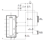
Switching MOSFET have breakdown voltage 725V, over primary winding of the standby transformet is Clamp-to-Rail circuits. Capacitor 2,2nF and Zerer diode 150V see picture
Diodes D3 Allow for Partial Recycling of Leakage Inductance Energy and Improve Efficiency. R1 Limit Peak Reverse Current and Provide Some High
Frequency Damping, and R3 Allows VZ1 to Work as a “Bleed” Instead of a Hard Clamp, to Improve Efficiency.
The destruction of the transistor can not occur. The question is the effect of EMC and efficiency?

PS.png
 

Status
Not open for further replies.

Part and Inventory Search

Welcome to EDABoard.com

Sponsor

Back
Top