Alloy
Advanced Member level 4
Hello guys.
I have an idea for a hacky solution for my PIC server project. Can you tell me if it will work out?
I want to do a PIC18F67J60 + H1102NL + RJ45 connector server.
BUT I have PIC18 soldered on TQFP breakout board and can't make a TQFP board myself.
So...
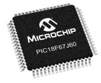
This is the MCU I will use:
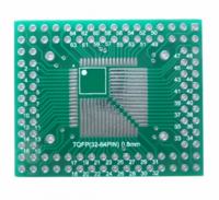
The MCU will be soldered on such board:
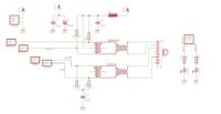
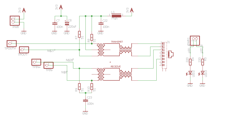
There will be also a RJ45 jack + H1102NL transformer PCB, schematic:
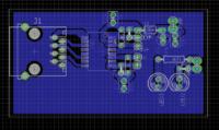
The RJ45 jack + H1102NL transformer PCB layout:
MCU board will be connected to the RJ45 board by short wires.
And my question is...
1. Will this work? Are such connections acceptable?
2. Can anyone check the schematic of RJ45 board, is this correct for PIC18F67J60 ?
3. What is the best value for that inductor on RJ45 board?
I have an idea for a hacky solution for my PIC server project. Can you tell me if it will work out?
I want to do a PIC18F67J60 + H1102NL + RJ45 connector server.
BUT I have PIC18 soldered on TQFP breakout board and can't make a TQFP board myself.
So...
This is the MCU I will use:
The MCU will be soldered on such board:
There will be also a RJ45 jack + H1102NL transformer PCB, schematic:
The RJ45 jack + H1102NL transformer PCB layout:
MCU board will be connected to the RJ45 board by short wires.
And my question is...
1. Will this work? Are such connections acceptable?
2. Can anyone check the schematic of RJ45 board, is this correct for PIC18F67J60 ?
3. What is the best value for that inductor on RJ45 board?