Continue to Site

Welcome to EDAboard.com

Welcome to our site! EDAboard.com is an international Electronics Discussion Forum focused on EDA software, circuits, schematics, books, theory, papers, asic, pld, 8051, DSP, Network, RF, Analog Design, PCB, Service Manuals... and a whole lot more! To participate you need to register. Registration is free. Click here to register now.

New Advanced Voltage Stabilizers (out-of-spec mains AC)

Status
Not open for further replies.

Almas Sahar

Newbie level 3
Joined
Dec 14, 2012
Messages
4
Helped
0
Reputation
2
Reaction score
1
Trophy points
1,281
Activity points
1,317
Dear

The usual voltage stabilizers that we use in our homes are either based on transformers and relays, or Servo motors and work on the concept of Tap Changing, however, I came to know about new techniques that use IGBTs and PWM, however I am not getting the clear picture of this.

Can someone please tell me any new advances in Stabilizers that make stabilizers cost effective, efficient and small size.

It would be better if it do not use conventional iron core bulky transformer but instead use ferrite core transformer.

Thanks
 
  • Like
Reactions: vestaengineering

    vestaengineering

    Points: 2
    Vesta engineering is the best company for Diesel generators and control panels. You can reach them
I think the technique you are referring to isn't to stabilize the incoming AC like the mechanical ones you describe. It actually re-creates a new AC signal using efficient PWM methods and IGBT or MOSFET power devices. It is a method with no moving parts or heavy iron transformers.

The working is like this:
1. incoming AC is rectified (maybe with PFC as well)
2. The DC goes through a first stage stabilizer, this may include a boost converter to cater for low input voltage
3. The DC is chopped by a PWM circuit to produce a high frequency carrier (~30KHz to 60KHz) carrying 50Hz/60Hz modulation.
4. The high frequency is filtered out, leaving mains AC as the result.

It allows for entirely electronic stabilization and the PWM and carrier are derived from a crystal source so the output AC is at a precise frequency and voltage.

Brian.
 

You are right but I need both Buck as well as Boost that is if I get 190 Volt from main supply still I get 220V from Output of Voltage Stabilizer, and if I get 250V from mains still I got an 220V AC, and to achieve this, I don't want to use conventional stabilizer that use sevo motor or Auto-transformer tapping.
 

An voltage converter with boost PFC or active front end will give you buck/boost capability by design.

What is your post targeting on? I presume designing/building a high frequency voltage stabilizer is over your head, you'll check the available retail products.
 

Quote: "The usual voltage stabilizers that we use in our homes". Maybe you are in a different world than mine?
I have never seen a "voltage stabilizer". My electricity network was designed to have good voltage regulation. My electricity voltage is 121V when everybody is using high current (air conditioners or Christmas tree lights) and is 123V when hardly any current is used by anybody.

The voltage variation you have is caused by poor design of your electricity network.
 

Canada has a good electricity supply network but many other countries do not, especially in rural areas. I doubt Almas has the financial resources to build new power stations and distribution networks across Pakistan.

You would be surprised at how many villages and small towns are entirely run from ancient Diesel generators and distribute over large distances at low voltage.

Brian.
 

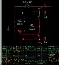
if I get 190 Volt from main supply still I get 220V from Output

This could be a feasible method to boost underspec mains AC. It starts as a voltage doubler (bridge type or Greinacher type). However the load is not positioned to receive DC.

The load is positioned to get AC. Transistors are biased at just the precise amount to feed an AC sinewave of the desired voltage to the load.


C values must be selected to store sufficient juice for the needed power. Increase C values for a greater boost ratio, or to power a heavier load.

If the load is light or absent, then voltages soar.

Power factor might need correcting. Insert inductors inline with the diodes.

- - - Updated - - -

The transistors must carry all power to the load. It's hard to be sure what they must withstand. Notice the outputs 1 & 2 are sine-shapes. Thus the transistors are not converting continuous DC to a sine. They do not need to dissipate extreme watt levels, but instead they are dropping several volts from a sine shape of a higher voltage to a lower voltage.
 

The usual voltage stabilizers that we use in our homes are either based on transformers and relays, or Servo motors and work on the concept of Tap Changing, however, I came to know about new techniques that use IGBTs and PWM, however I am not getting the clear picture of this.

You are perhaps referring to transformer-based AC voltage stabilizers employing the series regulation topology, which differently from the "conventional" tapped transformers, a few amount of smallest transformers with different voltage ratios either add or subtract voltage coming from the mains, achieving a better resolution if compared to a single multi-tap transformer.
 

Status
Not open for further replies.

Part and Inventory Search

Welcome to EDABoard.com

Sponsor

Back
Top