Continue to Site

Welcome to EDAboard.com

Welcome to our site! EDAboard.com is an international Electronics Discussion Forum focused on EDA software, circuits, schematics, books, theory, papers, asic, pld, 8051, DSP, Network, RF, Analog Design, PCB, Service Manuals... and a whole lot more! To participate you need to register. Registration is free. Click here to register now.

172.3MHz oscillator needed

Status
Not open for further replies.

neazoi

Advanced Member level 6
Joined
Jan 5, 2008
Messages
4,119
Helped
13
Reputation
26
Reaction score
15
Trophy points
1,318
Location
Greece
Activity points
36,918
Hi,
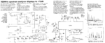
I need to build a simple but stable oscillator for 172.3MHz, to use in this spectrum analyzer, near the NE605.
(The circuit states 173.3 but it should be 172.3MHz, since the difference from the helical filter is 10.7MHz)

The problem is that such saw resonators are almost impossible to find!
So I am thinking of a harmonics (butler?) crystal oscillator, or a filtered comb generator, or a filtered harmonic of a can oscillator module.

But I have no idea about the input level required by the NE605.

Any ideas of how to make such an oscillator?
 

Attachments

  • spectrum analyzer.png
    spectrum analyzer.png
    848.4 KB · Views: 94
Last edited:

Hi,

use a PLL.

Klaus

A PLL is not a simple solution. Here only a simple oscillator is needed. A ceramic resonator or multiplied XO stability is adequate.
 

Change the first IF with a proper value so that your Xtal would be easily available.
You don't have to use 183 MHz helical filter, use another proper one associated with xtal..
 

See application note AN1994, says 200mV LO level.
Frank

Yes I have seen that now, thank you.

The sa605 can be operated with an LC as well and in fact it is suggested for frequencies greater than 170MHz. I wonder how good the LC stability would be in the configuration shown in the datasheet. Would it be adequate for the spectrum analyzer?

The helical filter has 4MHz (-1dB) bandwidth, so I guess a slight drift would not cause a serious problem other than seeing the signals on the screen drifting?

- - - Updated - - -

Change the first IF with a proper value so that your Xtal would be easily available.
You don't have to use 183 MHz helical filter, use another proper one associated with xtal..

I already obtained this hard to find filter...
 

Only two choices here that I can see.

Purchase a custom ground overtone crystal for 172.3 Mhz.
I recently ordered one for 73.500 Mhz, for a very similar application, still recovering from the $53.00 price shock though.
That is probably the simplest minimum components solution.

Another way to do it might be with a phase locked loop using an E-bay ready to run DDS circuit board.
**broken link removed**
Now these only go up to 70 Mhz output, and struggle to get even that high from a 180 Mhz clock source on the DDS board.

The trick would be to turn the DDS around, and drive it from a VCO running at 172.3 Mhz instead of the 180 Mhz internal clock.
You then program the DDS to provide any output frequency to match some other conveniently available reference source.
This can be ANY frequency from audio up to 70Mhz in about 0.04 Hz steps !

Then use that to phase lock your VCO to 172.3 Mhz (within maybe a couple of Hz). The DDS becomes in effect a divide by N counter with very fine resolution that you can set to better than one part in four billion fractional division.

Its still slightly complicated, because the DDS frequency (40 bits) needs to be programmed in at power up.
If your spectrum analyser already has a microcontroller, that should be very easy.

So you think the LC stability won't be enough, right?
I am thinking of using a T44-0 for the inductor and NP0 capacitors.
I have no idea how to monitor the oscillation out of the ne605 though, so I can measure it's frequency?

I was thinking also for a commonly available 10.7MHz square wave crystal oscillator module. I do not know if the 16th harmonic would be adequate to be filtered and amplified with a simple transistor amplifier, but I have seen some cheap amateur "comb generators" use just a single square wave oscillator. It may be that the 16th harmonic could be already 200mV to be fed directly to the chip after filtered.
It would give an output of 171.2MHz, which is about 1MHz off, but the heical filter I use, has +\-2MHz bandwidth (at -1db) so it should be fine I guess?
 

The fewer frequencies you generate, the fewer spurious "mystery" signals will make themselves right at home on your spectrum analyser.
A comb generator feeding into a broad band mixer would be about the very last thing you would want.
 
  • Like
Reactions: neazoi

    neazoi

    Points: 2
    Helpful Answer Positive Rating
The fewer frequencies you generate, the fewer spurious "mystery" signals will make themselves right at home on your spectrum analyser.
A comb generator feeding into a broad band mixer would be about the very last thing you would want.

Seeing the difficulty of the thing, I am thinking more and more the colpits LC conficuration.
See the attached ne605 chip datasheet at page 11 and 12.

I am thinking of using a T44-0 for the inductor and NP0 capacitors.
I have attached the data for the T44-0. It is a non magnetic core and it has 0ppm/C, meaning it should be quite stable. If combined with NP0 capacitors wouldn't it be stable enough for the purpose? The simplicity is of no match to other circuits and no lower spurious are produced.

I have no idea how to monitor the oscillation out of the ne605 though, so I can measure it's frequency?
Can I do it by taking the signal out of the pin 3 (emitter) using a small capacitor?
 

Attachments

  • AN1994-2.pdf
    3.2 MB · Views: 156
  • 1908_Amidon_T44-0_01.pdf
    178.5 KB · Views: 55

There were some IC circuits who have simple divider,PFD,charge pump circuits to generate a PLL locked frequency regarding to its reference frequency.These circuits were not programmable and they were working as compare and lock circuits.Seek internet, you can perhaps find them somewhere..
 

I found some IC simple OSC with very good performance.
Only 2-3 USD.
https://www.sitime.com/

They are preprogrammed for a specific frequency, aren't they?
Also they have square wave output aren't they? (eg SiT9102)

They remind me the Si570, preprogrammed for a single frequency.

Not of much use here, although good for clocking.
 

Yes, they are programmed at any freq you required.
It has a PLL setting.
It is very good for single freq, and has several options for stability.
 

How are these programmed ?
Do you order them already set to one of the alternative frequency choices.
Or is there some kind of do it yourself programming hardware required.
 

Hi, Warpspeed,
It's programmed by the vendor according to my choice.
I can't program it.
 

One example datasheet.
 

Attachments

  • SiT8209-datasheet.pdf
    661.7 KB · Views: 63

Status
Not open for further replies.

Part and Inventory Search

Welcome to EDABoard.com

Sponsor

Back
Top