Continue to Site

Welcome to EDAboard.com

Welcome to our site! EDAboard.com is an international Electronics Discussion Forum focused on EDA software, circuits, schematics, books, theory, papers, asic, pld, 8051, DSP, Network, RF, Analog Design, PCB, Service Manuals... and a whole lot more! To participate you need to register. Registration is free. Click here to register now.

I need to generate variable frequency in verilog

Status
Not open for further replies.

vivek_vlsi

Newbie level 4
Joined
Jul 25, 2016
Messages
6
Helped
0
Reputation
0
Reaction score
0
Trophy points
1
Activity points
45
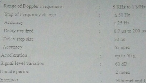
I need to generate a variable frequency 1Kz to 1Mhz in runtime from a 200 Mhz clock .
I need to use verilog and simulate in Modelsim.What are the possible ways?
 

Hi,

* PLL
* (integer) frequency divider
* NCO

Each one has its benefits and drawbacks.

Besides min and max frequency you need to know:
* allowed jitter
* frequency resolution
* effort of implementation
* do you need a certain (fixed or variable) duty cycle
* how and how fast do you want to change frequency?

Klaus
 
Looks like a university homework exercise...

Other than what is mentioned above, if you want to do it manually, you have to use various 200MHz freq divider logic. For that you need to write various counter logic in RTL.
 
Hi,

* PLL
* (integer) frequency divider
* NCO

Each one has its benefits and drawbacks.

Besides min and max frequency you need to know:
* allowed jitter
* frequency resolution
* effort of implementation
* do you need a certain (fixed or variable) duty cycle
* how and how fast do you want to change frequency?

Klaus

Thanks,

My target device is Spartan 6.I think i can use dds core which is nco available.
I went through the dds spec now.What i understood is we need to give Δθ ,the phase increment value to get a desired frequency.Can we vary the out put frequency dynamically by streaming phase increment values in input for a single channel? is Δθ is the only thing we need to vary to get variable frequency if we need constant frequency resolution and duty cycle.
 

Looks like a university homework exercise...

Other than what is mentioned above, if you want to do it manually, you have to use various 200MHz freq divider logic. For that you need to write various counter logic in RTL.

Hi,i used frq divider logic initially,but for my required range how many counters i need to use for pretty high resolution?
Also we cant use parameterized counter if synthesizing right?
 

Hi,

DDS means you need a special waveform, like sine?

****
how many counters i need to use for pretty high resolution?
Divider: (this is so simple you could do alone)
from 200MHz to 1kHz = 200M/1k = 200k = about 2^18. means: 18 bit counter.
from 200MHz ot 1MHz = 200

So you need a 18 bit counter generating (1 + 200k - 200 = 199800 different frequencies) with "compare" values from 200 up to 200000.

For clean square wave signals I recommend to toggle an output every compare match. = 2 compare match each full wave
This needs a counter of 17 bit and compare match values 100 to 99900.

The clean divider solution has a 10ns timing resolution for generating the frequency. It generates very low jitter. It has very good frequency resolution at low frequencies but poor resulution at high frequencies.
*****

The NCO solution gives a frequency resolution in unique frequency steps. Frequency resolution depends on (fractional) adder/integrator resolution. It generates some frequency jitter.

Klaus
 
Hi,

DDS means you need a special waveform, like sine?

****

Divider: (this is so simple you could do alone)
from 200MHz to 1kHz = 200M/1k = 200k = about 2^18. means: 18 bit counter.
from 200MHz ot 1MHz = 200

So you need a 18 bit counter generating (1 + 200k - 200 = 199800 different frequencies) with "compare" values from 200 up to 200000.

For clean square wave signals I recommend to toggle an output every compare match. = 2 compare match each full wave
This needs a counter of 17 bit and compare match values 100 to 99900.

The clean divider solution has a 10ns timing resolution for generating the frequency. It generates very low jitter. It has very good frequency resolution at low frequencies but poor resulution at high frequencies.
*****

The NCO solution gives a frequency resolution in unique frequency steps. Frequency resolution depends on (fractional) adder/integrator resolution. It generates some frequency jitter.

Klaus

Hi,It was all good with your help.Now I have to incorporate velocity,acceleration and Doppler shift to the sine wave generated.We need to assume this sine wave is generated from a moving object.Hope you got the idea.How can we vary the frequency and amplitude of the sine wave w.r.t these parameters.I need to simulate that scenario in verilog.
 

Hi,

My solution is about generating a square wave. (You didn´t answer my question about wavefrom).

Now you talk about sine. I wonder how you generate the sine?

***
And doppler means two frequencies
* the original one
* and the reflected one.

Or how else is your doppler situation?

*******

Please provide complete informations. Drafts, schematics, ideas....Without it we can just guess.

Klaus

its sine wave only .using LUT i generated.values got from MATLAB.
frequency i varied accoring to your solution.its simulation of reflected wave required.how the velocity and acceleration of the moving body affect the generated sine wave from it.We can input velocity and acceleration to sine wave generation.I am also having this much idea provided with.
 

Status
Not open for further replies.

Part and Inventory Search

Welcome to EDABoard.com

Sponsor

Back
Top