renga92
Member level 5
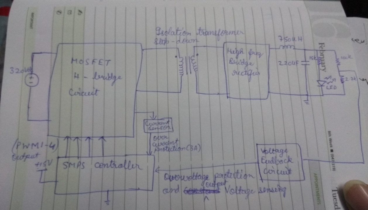
Hi Everyone. I am designing a 400W SMPS design[Max voltage : 200V Max Amp : 2A]. One completion of the design I tried to test it by connecting a 100 ohm 200W load to it. I made sure output voltage be set at 100V and over current protection at 3A. When I did turn it on, it drew only 100mA from the source and output voltage was only 36V. I guess SMPS could not source the current for the required load.
To debug I connected the load directly to the secondary of the isolation transformer bypassing rest of the circuit in the secondary and it was drawing 1.6A.[ Output voltage : 160V]
Then I connected it to the secondary high frequency rectifier diode and it was able to source around 1.6A bypassing the filter circuit. [Output voltage : 160V].
Then when I connected secondary circuit to the filter circuit, again the SMPS drew only 100mA from the source. I guess the filter consisting of the L = 750uH (T27 core) and cap = 220uF is the problem. I tried removing the load and then the open circuit output voltage was 100V.
Source could not see the resistive load and hence no current is flowing through it. Can you help me out with the filter design to make the SMPS work.