Continue to Site

Welcome to EDAboard.com

Welcome to our site! EDAboard.com is an international Electronics Discussion Forum focused on EDA software, circuits, schematics, books, theory, papers, asic, pld, 8051, DSP, Network, RF, Analog Design, PCB, Service Manuals... and a whole lot more! To participate you need to register. Registration is free. Click here to register now.

P spice problem, from good inputs I take a bad output

Status
Not open for further replies.

joyam

Newbie level 3
Joined
Jul 21, 2016
Messages
4
Helped
0
Reputation
0
Reaction score
0
Trophy points
1
Activity points
35
Pspice problem , from good inputs i take a bad output

Hello there i have a problem with p spice and i dont know what to do with it since no actual error emerges. I am attaching a self explanatory immage, any help would be greatly apreciated Screenshot_4.png
 

Re: Pspice problem , from good inputs i take a bad output

There looks to be no activity and I also see no power supplies
nor ground, which might be why? Even what should be stimuli
(a, b, cin) seem to be doing nothing. Your output plot lacks
any info that might let us check whether output is correct for
the input state (levels).

I'd start with drilling into one of the gates and see if it's even
powered. Assuming this is SPICE mode and not some verilog
digital deal, which doesn't care about such things.
 

Re: Pspice problem , from good inputs i take a bad output

potential race conditions... are inputs synchronized?
they ought to be.
Hello there, i dont have any flip flops in any other hierarchy level, is there another way a race could be created ? (sorry but i am still a novice )

There looks to be no activity and I also see no power supplies
nor ground, which might be why? Even what should be stimuli
(a, b, cin) seem to be doing nothing. Your output plot lacks
any info that might let us check whether output is correct for
the input state (levels).

I'd start with drilling into one of the gates and see if it's even
powered. Assuming this is SPICE mode and not some verilog
digital deal, which doesn't care about such things.
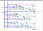
I am using capture cis program from orcad (if i describe it correct ). I can supply you with images from the upper hierarchy levels.What i am trying to create is a 16 bit unsigned array multiplier. If i replace the xor gate on that full adder with an and gate for example it gives an output but not the one i want :p

All your help is greatly appreciated .Screenshot_8.pngScreenshot_9.pngScreenshot_10.png
 

Re: Pspice problem , from good inputs i take a bad output

OK, but still my original questions remain - I see no "output"
in the sense of anything changing signal-wise, and I see no
explicit application of power to the whole ensemble at any
of the levels shown thus far. So I still recommend you probe
down in the guts of the logic gates to see if, at any level,
they have "live" power and stimulus, and thus a valid (even
just locally) output.

Thanks for your answer
Probably due to lack of experience i dont really understand your question .
The 32 bit bus should be the output in the way i see it while the two stim sources in the input give the power . As for the gates i dont think i can see whats inside of them they are components i have taken from digprim library.
 

Re: Pspice problem , from good inputs i take a bad output

If this is truly a "digital" simulation then perhaps this is true
but I would not take that for granted in a SPICE or even a
mixed-mode simulator.

Maybe take a big step back and try to run just one simple
dumb inverter from that library, something you can easily
see if it's working or not. If you're juggling chainsaws, try
starting with just one.

Even a veriloga style digital model will need a positive and
negative supply pair (although lazy implementations may
make the negative implicitly GND). Only a true digital verilog
model won't care that no power source exists.

Why don't you try and switch-view into the digprim gate
to see if there's a schematic layer below, because if so
maybe it uses global nets which you have to power from
the testbench schematic using sources and global-ties.
 

Re: Pspice problem , from good inputs i take a bad output

Thanks a lot for your help, i managed to make it work.The reason it was not working was the names of cables and buses, i managed to find names that worked with the trial and error method so i am not 100% sure what was wrong.
Once more thank you
 

Status
Not open for further replies.

Part and Inventory Search

Welcome to EDABoard.com

Sponsor

Back
Top