Dr. von Rosenstein
Member level 1
Hi,
if I understand this right, then Load-Pull means, that a load with a tunable impedance is connected to the output of a circuit (for example an amplifier). Then this impedance is varied and the power which is delivered to this load is observed. If this power is at its maximum, the corresponding impedance is the complex conjugated of the output-impedance of the actual circuit (the amplifier). Is this right?
The same method should work to find the input-impedance of a circuit (Source-Pull?).
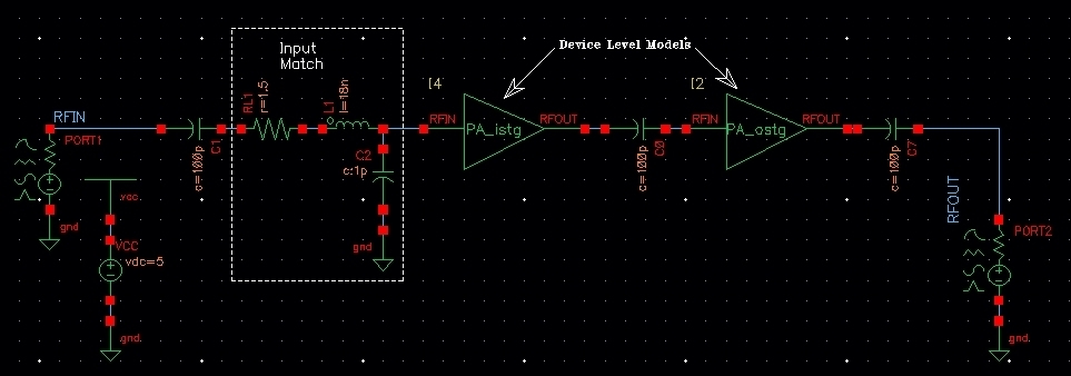
I read in the "SpectreRf Workshop" PDF about "Power Amplifier Design Using SpectreRf" the chapter about "Load-Pull Measurements". I simulated the example circuit and everything was fine.
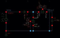
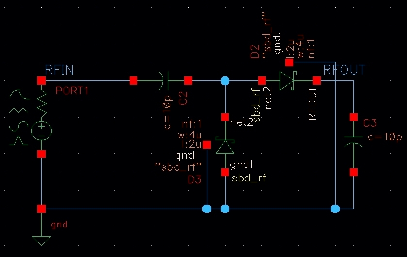
My goal is to find the input-impedance of a simple rectifier (the impedance, at which the output-DC-voltage is at its maximum).
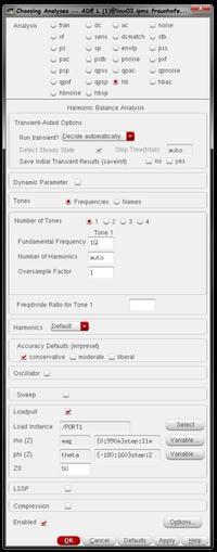
This is the analyses form:
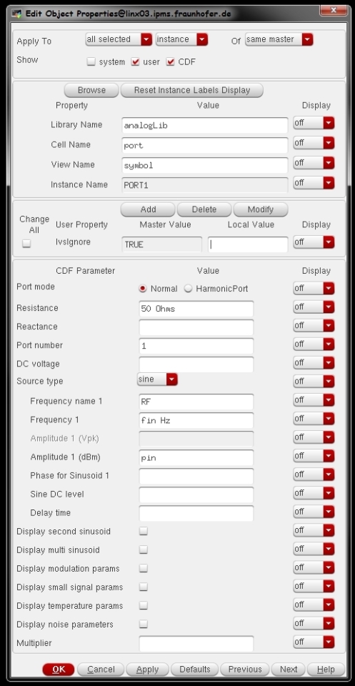
And this is the properties form of the port:

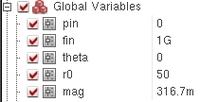
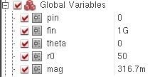
The variables:
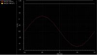
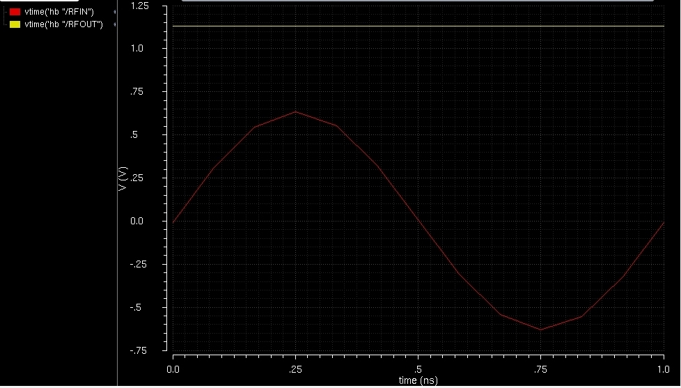
If I do a normal hb- oder pss-simulation (normal means: no load-pull) the simulation results are as expected.
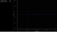
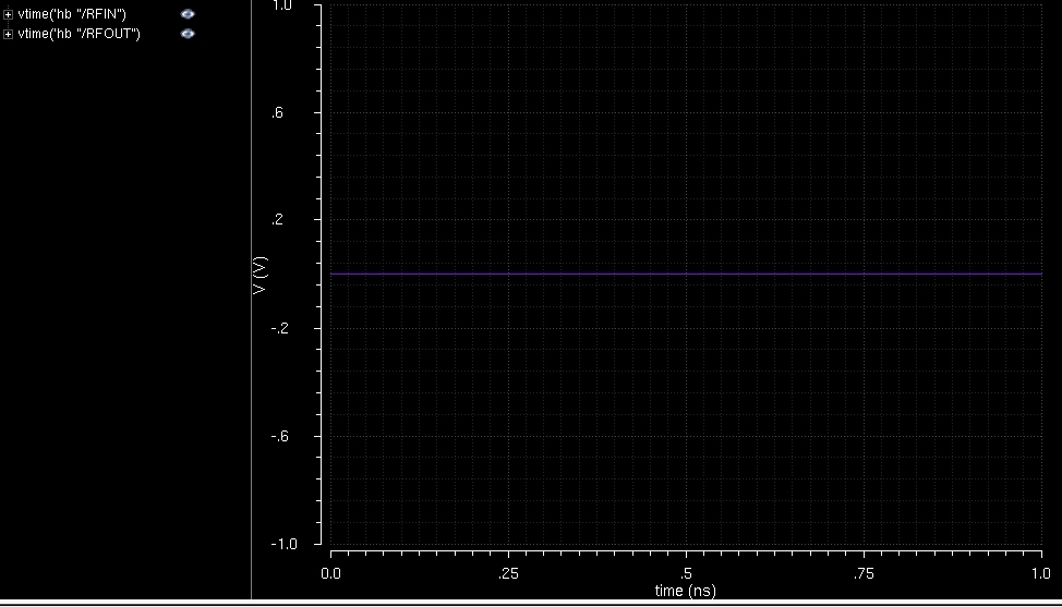
But with activated load-pull, the port delivers always 0 W (RFIN is in the order of E-171 V).
What am I doing wrong?
I tested this with only an inductor instead of the rectifier. Same result: without load-pull everything is fine, with load-pull everything is zero.
Additional question: Can anyone explain me, why I have to fill in 50 Ohm? At 3 places: Z0 in the analyses form, resistance in the port-properties, r0 in the variables. I thougt, that the impedance is varied. But where are these 50 Ohms used?
Please help me!
Thank you!
Sascha
if I understand this right, then Load-Pull means, that a load with a tunable impedance is connected to the output of a circuit (for example an amplifier). Then this impedance is varied and the power which is delivered to this load is observed. If this power is at its maximum, the corresponding impedance is the complex conjugated of the output-impedance of the actual circuit (the amplifier). Is this right?
The same method should work to find the input-impedance of a circuit (Source-Pull?).
I read in the "SpectreRf Workshop" PDF about "Power Amplifier Design Using SpectreRf" the chapter about "Load-Pull Measurements". I simulated the example circuit and everything was fine.
My goal is to find the input-impedance of a simple rectifier (the impedance, at which the output-DC-voltage is at its maximum).
This is the analyses form:

And this is the properties form of the port:
The variables:
If I do a normal hb- oder pss-simulation (normal means: no load-pull) the simulation results are as expected.
But with activated load-pull, the port delivers always 0 W (RFIN is in the order of E-171 V).
What am I doing wrong?
I tested this with only an inductor instead of the rectifier. Same result: without load-pull everything is fine, with load-pull everything is zero.
Additional question: Can anyone explain me, why I have to fill in 50 Ohm? At 3 places: Z0 in the analyses form, resistance in the port-properties, r0 in the variables. I thougt, that the impedance is varied. But where are these 50 Ohms used?
Please help me!
Thank you!
Sascha
Last edited by a moderator: