Continue to Site

Welcome to EDAboard.com

Welcome to our site! EDAboard.com is an international Electronics Discussion Forum focused on EDA software, circuits, schematics, books, theory, papers, asic, pld, 8051, DSP, Network, RF, Analog Design, PCB, Service Manuals... and a whole lot more! To participate you need to register. Registration is free. Click here to register now.

[SOLVED] Interfacing P10 LED matrix module with PIC16F1939.

Status
Not open for further replies.

pravin b

Member level 5
Joined
May 20, 2012
Messages
85
Helped
2
Reputation
4
Reaction score
1
Trophy points
1,288
Location
Mumbai, India
Activity points
2,083
Hello Friends,
I am trying to interface the p10 led matrix display module with pic16f1939 running at 32MHz internal clock, MPLABx & HI TECH C Compiler.
To send the data to display I am using software spi routine (attached below). and regarding the protocol details I am referring DMD Notes.txt found here
HTML:
 http://forum.freetronics.com/viewtopic.php?t=5754
. Since "i think" i am doing same as specified in the txt file, however I dont see anything on my display, its just blank. It would be nice if someone can help me. I have written a code to display "abcd" on the display through 16*4 array.
my main code
Code:
#include <htc.h>
#include "include.h"

// PIC16F1939 Configuration Bit Settings
__CONFIG(FOSC_INTOSC & WDTE_OFF & PWRTE_ON & MCLRE_ON & CP_OFF & CPD_OFF & BOREN_OFF & CLKOUTEN_OFF & IESO_OFF & FCMEN_OFF);
__CONFIG(WRT_OFF & VCAPEN_OFF & PLLEN_ON & STVREN_ON & BORV_LO & LVP_OFF);

//                                a    b    c    d                     
unsigned char dmdbuff[16][4]={//C0    C1   C2   C3
                                {0x00,0x00,0x00,0x00},  //R0
                                {0x00,0x00,0x00,0x00},  //R1
                                {0x00,0x00,0x00,0x00},  //R2
                                {0x00,0x00,0x00,0x00},  //R3
                                {0x00,0x00,0x00,0x00},  //R4
                                {0x00,0x00,0x00,0x00},  //R5
                                {0x00,0x00,0x00,0x00},  //R6
                                {0x00,0x00,0x00,0x00},  //R7
                                {0x00,0x20,0x00,0x04},  //R8
                                {0x38,0x20,0x38,0x04},  //R9
                                {0x44,0x2c,0x44,0x34},  //R10
                                {0x04,0x32,0x40,0x4c},  //R11
                                {0x3c,0x22,0x40,0x44},  //R12
                                {0x44,0x32,0x40,0x44},  //R13
                                {0x44,0x32,0x44,0x4c},  //R14
                                {0x38,0x2c,0x38,0x34},  //R15 
                            };

char row,x,y;
void main()
{
    system_init();
    while(1)
    {        
        show_row(0);        
        show_row(1);
        show_row(2);
        show_row(3); 
    }
}


void system_init()
{
    OSCCON  = 0b01110000;   // 32 MHz Fosc w/ PLLEN_ON (config bit) 
    TRISC=0b00000000;
//    PORTC=0;
    TRISD0=0;
    pin=0;
//    USART_Init();
//    ms1_delay(100);
//    USART_putstring("UART_OK\r");
    swspi_init();
}

void show_row(char temp)
{        
    for(y=0;y<=3;y++)
    {
        swspi_write_byte(dmdbuff[(16-4)+temp][y]); 
        swspi_write_byte(dmdbuff[(16-8)+temp][y]);
        swspi_write_byte(dmdbuff[(16-12)+temp][y]);
        swspi_write_byte(dmdbuff[(16-16)+temp][y]);               
    }
    
    P10_LATCH=1;
    us500_delay(1);
    P10_LATCH=0;
    
    scan_row(temp); 
    
    DISP_EN=0;    
}

void scan_row(char temp)
{
    switch(temp)
    {
        case 0: P10_A=0;
                P10_B=0;
            break;
        case 1: P10_A=1;
                P10_B=0;
            break;
        case 2: P10_A=0;
                P10_B=1;
            break;
        case 3: P10_A=1;
                P10_B=1;
            break;
        default:P10_A=0;
                P10_B=0;
            break;            
    }
}

void ms1_delay(unsigned int c)          
{
    unsigned int i,j;
    for(i=1;i<=c;i++)
        for(j=0;j<=568;j++);
}

void us500_delay(unsigned int c)          
{
    unsigned int i,j;
    for(i=1;i<=c;i++)
        for(j=0;j<=284;j++);
}

void interrupt my_ISR()
{
    if(RCIF)
    {
        USARTdataready=1;
        rx_byte=RCREG;
        if(FERR || OERR)
            CREN=0;
        USART_putchar(rx_byte);
        RCIF=0;
        get_data();          
    }
}

my spi routine

Code:
void swspi_init( void )
{
    P10_A=0;
    P10_B=0;
    P10_PWM=0;
    P10_SCK=0;
    DISP_EN=1;    
    P10_DATA=0;
    P10_LATCH=0;
}

/*************************************
write value to register
**************************************/
void swspi_write_byte(unsigned int temp)
{
	unsigned char n=8;
//    DISP_EN = 0;

//	temp |= 0x80;

//  	P10_SCK = 0;
  	while(n--)
   	{
        P10_SCK = 0;
     	if(temp&0x80)
      		P10_DATA=1;
     	else
      		P10_DATA=0;
              
        P10_SCK = 1;
        temp <<= 1;		
   	}
	NOP();
//	DISP_EN = 1;	
}

pin assignment

Code:
#define  P10_A    	RC0
#define  P10_B    	RC1
#define  P10_PWM	RC2
#define  P10_SCK	RC3
#define  DISP_EN    RC4
#define  P10_DATA   RC5
#define  P10_LATCH	RC6

Thanks!
 

Hi pravin,
I think you are trying to run ...before you can walk.

Please follow the following steps:
1. Turn ON, only one Row and One Column: Only ONE LED must Turn ON.
If it is NOT turning ON, then check your program and/or hardware. whether the voltage on these pins is as per your written program or NOT.

2. Turn ON One whole ROW or Column. Check whether the corresponding Row or Column is Turning ON or NOT. If it is NOT turning ON, then then check your program and/or hardware. whether the voltage on these pins is as per your written program or NOT.

I think you should attempt to complete the above 2 tasks even before you write the software for the whole display.

If I was in your place...I would follow the above steps.

Kiran V Sutar
 
yes definitely sir. Thanks for your kind reply.
But I have to ensure that if i am sending the bytes to led matrix in correct order or not? for example

adresleme-yapisi.png

in the along with image, what should be the order of sending bytes to display??? Currently I am sending as :
Code:
call of showrow(0):DisplayRam[12][0]>DisplayRam[8][0]>DisplayRam[4][0]>DisplayRam[0][0]>DisplayRam[13][0]>DisplayRam[9][0]>DisplayRam[5][0]>DisplayRam[1][0]>DisplayRam[14][0]>DisplayRam[10][0]>DisplayRam[6][0]>DisplayRam[2][0]>DisplayRam[15][0]>DisplayRam[11][0]>DisplayRam[7][0]>DisplayRam[3][0]

call of showrow(1):DisplayRam[12][1]>DisplayRam[8][1]>DisplayRam[4][1]>DisplayRam[0][1]>DisplayRam[13][1]>DisplayRam[9][1]>DisplayRam[5][1]>DisplayRam[1][1]>DisplayRam[14][1]>DisplayRam[10][1]>DisplayRam[6][1]>DisplayRam[2][1]>DisplayRam[15][1]>DisplayRam[11][1]>DisplayRam[7][1]>DisplayRam[3][1]

& so on....

so is that the correct order? HOwever I am still having trouble making 1 pixel ON at a time, checking my hardware if any of lines need a pullup?
 

Pins on one side of the matrix display connect to anodes and the pins on another side connect to cathodes. Have you connected anodes and cathodes properly ?
 
Pins on one side of the matrix display connect to anodes and the pins on another side connect to cathodes. Have you connected anodes and cathodes properly ?
Doesn't apply here. "P10" LED module is a ready made module with serial mux interface.

Unfortunately it's not clearly mentioned in the initial post.
 
**broken link removed** the datasheet available here
 
Thanks friends for your help.
@KiranVSutar yes I am following the same path as you mentioned.
@Okada P10 module has internal MUX circuitry, I have to just send the data on SPI bus.
@FvM just noticed that, updating the title.
@Thannara123 I have read the datasheet.​

however, now I am able to turn on the LEDs, for example if i send 0xff; 8 LEDs turns ON, but of the wrong row.
For example when I send data to row2 the data get displayed on row3. Wrt row-col table in post #3 it seems like my even number of rows are not glowing any time. I checked on UART interface the row selection values (A & B) seems OK. They changes as per show_row(x) in main. Not getting where I am going wrong.
Here is my updated code
Code:
#include <htc.h>
#include "include.h"

// PIC16F1939 Configuration Bit Settings
__CONFIG(FOSC_INTOSC & WDTE_OFF & PWRTE_ON & MCLRE_ON & CP_OFF & CPD_OFF & BOREN_OFF & CLKOUTEN_OFF & IESO_OFF & FCMEN_OFF);
__CONFIG(WRT_OFF & VCAPEN_OFF & PLLEN_ON & STVREN_ON & BORV_LO & LVP_OFF);

////                                a    b    c    d                     
//unsigned char dmdbuff[16][4]={//C0    C1   C2   C3
//                                {0x00,0x00,0x00,0x00},  //R0
//                                {0x00,0x00,0x00,0x00},  //R1
//                                {0x00,0x00,0x00,0x00},  //R2
//                                {0x00,0x00,0x00,0x00},  //R3
//                                {0x00,0x00,0x00,0x00},  //R4
//                                {0x00,0x00,0x00,0x00},  //R5
//                                {0x00,0x00,0x00,0x00},  //R6
//                                {0x00,0x00,0x00,0x00},  //R7
//                                {0x00,0x20,0x00,0x04},  //R8
//                                {0x38,0x20,0x38,0x04},  //R9
//                                {0x44,0x2c,0x44,0x34},  //R10
//                                {0x04,0x32,0x40,0x4c},  //R11
//                                {0x3c,0x22,0x40,0x44},  //R12
//                                {0x44,0x32,0x40,0x44},  //R13
//                                {0x44,0x32,0x44,0x4c},  //R14
//                                {0x38,0x2c,0x38,0x34},  //R15 
//                            };


unsigned char dmdbuff[16][4]={//C0    C8   C16  C24C31
                                {0x00,0x00,0x00,0x00},  //R0
                                {0xFF,0x00,0x00,0x00},  //R1
                                {0xFF,0x00,0x00,0x00},  //R2
                                {0x00,0x00,0x00,0x00},  //R3
                                {0x00,0x00,0x00,0x00},  //R4
                                {0x00,0x00,0x00,0x00},  //R5
                                {0x00,0x00,0x00,0x00},  //R6
                                {0x00,0x00,0x00,0x00},  //R7
                                {0x00,0x00,0x00,0x00},  //R8
                                {0x00,0x00,0x00,0x00},  //R9
                                {0x00,0x00,0x00,0x00},  //R10
                                {0x00,0x00,0x00,0x00},  //R11
                                {0x00,0x00,0x00,0x00},  //R12
                                {0x00,0x00,0x00,0x00},  //R13
                                {0x00,0x00,0x00,0x00},  //R14
                                {0x00,0x00,0x00,0x00},  //R15 
                            };
char y;
void main()
{
    system_init();
    while(1)
    {           
        show_row(0);        
        show_row(1);
        show_row(2);
        show_row(3); 
//        while(1);
    }
}


void system_init()
{
    OSCCON  = 0b01110000;   // 32 MHz Fosc w/ PLLEN_ON (config bit) 
    TRISA=0b11111111;
    TRISB=0b11111111;
    TRISC=0b00000000;    
    TRISD=0b11111110;
    TRISE=0b1111;   
    
    pin=0;
    
    USART_Init();
    ms1_delay(100);
    USART_putstring("UART_OK\r");
    swspi_init();
}

void show_row(char temp1)
{   
    DISP_EN=1;
    scan_row(temp1); 
    for(y=0;y<=3;y++)
    {
        swspi_write_byte(~dmdbuff[(16-4)+temp1][y]); 
//        sprintf(sbuff,"X-%02d, Y-%02d\r",(16-4)+temp1,y);     //for debugging on UART
//        USART_putstring(sbuff);                               //for debugging on UART
        swspi_write_byte(~dmdbuff[(16-8)+temp1][y]);
//        sprintf(sbuff,"X-%02d, Y-%02d\r",(16-8)+temp1,y);     //for debugging on UART
//        USART_putstring(sbuff);                               //for debugging on UART
        swspi_write_byte(~dmdbuff[(16-12)+temp1][y]);
//        sprintf(sbuff,"X-%02d, Y-%02d\r",(16-12)+temp1,y);    //for debugging on UART
//        USART_putstring(sbuff);                               //for debugging on UART
        swspi_write_byte(~dmdbuff[(16-16)+temp1][y]);   
//        sprintf(sbuff,"X-%02d, Y-%02d\r",(16-16)+temp1,y);    //for debugging on UART
//        USART_putstring(sbuff);                               //for debugging on UART
    }
    
    P10_LATCH=1;
    us5_delay(1);
    P10_LATCH=0;
    
    DISP_EN=0; 
//    us500_delay(1);
    
}

void scan_row(char temp2)
{
    switch(temp2)
    {
        case 0: P10_A=0;
                P10_B=0;                
            break;
        case 1: P10_A=1;
                P10_B=0;                
            break;
        case 2: P10_A=0;
                P10_B=1;                
            break;
        case 3: P10_A=1;
                P10_B=1;                
            break;
        default:P10_A=0;
                P10_B=0;                
            break;            
    }
//    sprintf(sbuff,"%d_A=%d, B=%d\r",temp2,P10_A,P10_B);
//    USART_putstring(sbuff);
}

void ms1_delay(unsigned int c)          
{
    unsigned int i,j;
    for(i=1;i<=c;i++)
        for(j=0;j<=568;j++);
}

void us500_delay(unsigned int c)          
{
    unsigned int i,j;
    for(i=1;i<=c;i++)
        for(j=0;j<=284;j++);
}

void us5_delay(unsigned int c)          
{
    unsigned int i;
    for(i=1;i<=c;i++)
    {
        NOP();
               
    }
}
void interrupt my_ISR()
{
    if(RCIF)
    {
        USARTdataready=1;
        rx_byte=RCREG;
        if(FERR || OERR)
            CREN=0;
        USART_putchar(rx_byte);
        RCIF=0;
        get_data();          
    }
}

update: how can i modify the title?
 
Last edited:

Hello friends,
Thanks for your support.
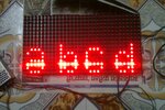
Finally succeeded to display "abcd" on my single DMD. Here is the picture...:) :):)

PIMAG0272.jpg

However,
1. How can I make the light spot (due to upper ON LED) disappear?
2. Also how can I control the brightness of the display? I know I can use the PWM technique with OE, and I tried to do so but I get this result, That line between characters in image...

IMAG0273.jpg

I am implementing PWM in my code after calling scan_row(temp1) as follows in function show_row():
Code:
void show_row(char temp1)
{   
//    P10_EN=1;
    for(y=0;y<=3;y++)
    {
        swspi_write_byte(~dmdbuff[(16-4)+temp1][y]); 
        swspi_write_byte(~dmdbuff[(16-8)+temp1][y]);
        swspi_write_byte(~dmdbuff[(16-12)+temp1][y]);
        swspi_write_byte(~dmdbuff[(16-16)+temp1][y]);   
//        sprintf(sbuff,"X-%02d, Y-%02d\r_A=%d, B=%d; temp1=%d\r",(16-16)+temp1,y,P10_A,P10_B,temp1);     //for debugging on UART
//        USART_putstring(sbuff);                               //for debugging on UART
    }
    
    P10_LATCH=1;
    us5_delay(1);
    P10_LATCH=0;
    scan_row(temp1); 
    P10_EN=1;
    us5_delay(10);
    P10_EN=0; 
    us5_delay(180);    
}
it would be nice & helpful if someone can shed some light on the above techniques.
Oh yes and the problem was due to the golden rule i forgot to apply...."read from the PORT, write to the LAT."
Thanks again!:-D
Regards,
Pravin
 

Hello Friends, still fighting to get the solutions for above problem of "line in-between the text".
However I am following the following sequence in my program:
1. write data to 16 shift registers through SPI bus.
2. toggle clock.
3. Select appropriate row using A & B values.
4. Enable p10 display.
5. after some delay disable p10 display.

I am implementing PWM like effect between steps 4-5 to control the brightness.
Am I following the right procedure? please correct me if I am wrong or let me know if I can use anything else to control the brightness.
Thanks.

Pravin
 

hi friends, so far now I am able to display steady and moving message on the display, however i can see "ghosting" of one column behind each character. like, if character 'I' is one column long, i see there are two columns getting ON. how can I avoid this? th problem is perticularly for moving display only.
 

@FvM timing? as in what timing? SPI clock? I am using hardware spi in pic microcontroller with 32MHz frequency with SSPM<3:0> set to 0000 i.e clock=Fosc/4=8MHz which is max i can go. What should be the frequncy or how can i determine the correct frequency to operate at?
however i tried the lower clk rates to Fosc/16 & Fosc/64, still getting the same results with reduced speed (as expected).
@SunnySkyguy... thanks for the sharing the link as discussed in link, if i understood right this should work at 8MHz....correct me if I am wrong. Or do you mean i shall look into hardware part?
I am using self assembled & soldered general purpose PCB. Here is my code if you see something incorrect or just need to be modify.

Code:
/* scrolling effects:
 *show_string(0,"abcd") - Scrolls text Right to Left (default mode)
 *show_string(1,"abcd") - Scrolls text Left to Right
 * problem: scroll left to right yet to be checked.
 */

#include "include.h"
#include "myfont.h"
//#include "Terminal_font_12x16.h"

// PIC16F1939 Configuration Bit Settings
__CONFIG(FOSC_INTOSC & WDTE_OFF & PWRTE_ON & MCLRE_ON & CP_OFF & CPD_OFF & BOREN_OFF & CLKOUTEN_OFF & IESO_OFF & FCMEN_OFF);
__CONFIG(WRT_OFF & VCAPEN_OFF & PLLEN_ON & STVREN_ON & BORV_LO & LVP_OFF);

////                                a    b    c    d                     
/*unsigned char dmdbuff[16][4]={//C0    C1   C2   C3
                                {0x00,0x00,0x00,0x00},  //R0
                                {0x00,0x00,0x00,0x00},  //R1
                                {0x00,0x00,0x00,0x00},  //R2
                                {0x00,0x00,0x00,0x00},  //R3
                                {0x00,0x00,0x00,0x00},  //R4
                                {0x00,0x00,0x00,0x00},  //R5
                                {0x00,0x00,0x00,0x00},  //R6
                                {0x00,0x00,0x00,0x00},  //R7
                                {0x00,0x20,0x00,0x04},  //R8
                                {0x38,0x20,0x38,0x04},  //R9
                                {0x44,0x2c,0x44,0x34},  //R10
                                {0x04,0x32,0x40,0x4c},  //R11
                                {0x3c,0x22,0x40,0x44},  //R12
                                {0x44,0x32,0x40,0x44},  //R13
                                {0x44,0x32,0x44,0x4c},  //R14
                                {0x38,0x2c,0x38,0x34},  //R15 
                            };*/

unsigned char dmdbuff[16][4]={0};
char y,k=3,rcount=0;
void main()
{
    system_init();
    while(1)
    {        
        show_string(0,"hello world");
    }
}

void system_init()
{
    OSCCON  = 0b01110000;   // 32 MHz Fosc w/ PLLEN_ON (config bit) 

    TRISA=0b11111111;
    TRISB=0b11111111;
    TRISD=0b11111110;
    TRISE=0b1111;   
    
    test_led=0;
    test_led_DIR=0;
    
    USART_Init();
    ms1_delay(100);
    USART_putstring("UART_OK\r");
    hwspi_init();
    timer1_init();
}

void clear_display()
{
    char crow,ccol;
    for(crow=0;crow<16;crow++)
    {
        hwspi_write_byte(0xff);
    }
    P10_LATCH=1;
    NOP();
    NOP();
    P10_LATCH=0;
}

void show_row(char temp1)
{      
    for(y=0;y<=3;y++)
    {
        hwspi_write_byte(~dmdbuff[(16-4)+temp1][y]); 
        hwspi_write_byte(~dmdbuff[(16-8)+temp1][y]); 
        hwspi_write_byte(~dmdbuff[(16-12)+temp1][y]);
        hwspi_write_byte(~dmdbuff[(16-16)+temp1][y]);   
//        sprintf(sbuff,"X=%02d, Y=%02d, temp1=%d\r_A=%d, B=%d\r",(16-16)+temp1,y,temp1,P10_A,P10_B);     //for debugging on UART
//        USART_putstring(sbuff);                               //for debugging on UART
    }
    
    P10_LATCH=1;
    NOP();
    NOP();
    P10_LATCH=0;
}

void update_display_R_L(unsigned int pos)
{
	char fontwidth, row, col,width,m;
    width=font8x8[pos][0];
    
	for(fontwidth=0;fontwidth<=7;fontwidth++)
    {
        for(row=0;row<=15;row++)
        {
            for(col=0;col<=3;col++)
            {
                dmdbuff[row][col]<<=1;
                if(col<3)
                {
                    if(dmdbuff[row][col+1]&0x80)
                        dmdbuff[row][col]|=0x01;
                }
                else
                {
                    if(font8x8[pos][row]&(0x80>>fontwidth))
                        dmdbuff[row][col]|=0x01;
                }                
            }           
        }
        ms1_delay(50);		  //increase delay count to reduce speed.	
        
    }
}

void update_display_L_R(unsigned int pos)
{
	signed char fontwidth, row, width, col, m;
    width=font8x8[pos][0];
//    test_led=1;
	for(fontwidth=0;fontwidth<=7;fontwidth++)
    {
        for(row=0;row<=15;row++)
        {
            for(col=3;col>=0;col--)
            {
                dmdbuff[row][col]>>=1;
                if(col>0)
                {
                    if(dmdbuff[row][col-1]&0x01)
                        dmdbuff[row][col]|=0x80;                    
                }
                else if(col==0)
                {
                    if(font8x8[pos][row]&(0x01<<fontwidth))
                        dmdbuff[row][col]|=0x80;                    
                }   
            }           
        }
//        test_led=0;
//        display();
        ms1_delay(50);		  //increase delay count to reduce speed.	
        
    }
//    for(m=0;m<=15;m++)
//    {
//    sprintf(sbuff,"AL%03d, %03d, %03d, %03d\r",dmdbuff[m][0],dmdbuff[m][1],dmdbuff[m][2],dmdbuff[m][3]);
//    USART_putstring(sbuff);
//    }
}

void show_string(char style, char *str1)			 
{
    signed char i,msg_len, row, instring[5], col,m;
    char ;  
//	if(dupdate)
//		msg_len=slen;
//	else
		msg_len=strlen(str1);
        if(msg_len<5)
        {   
//            strcpy(instring,str1);
//            str1[msg_len]='a'
//            sprintf(sbuff,"old str: %s\r",instring);
//            USART_putstring(sbuff);;
//            strncat(instring,"    ",4-msg_len);
//            USART_putstring(instring);
                        
            for(col=0;col<msg_len;col++)
            {
                for(row=0;row<=15;row++)
                {
                    dmdbuff[row][col]=font8x8[(*str1)-32][row];
                }                
                str1++;                
            }
        }
        else
        {
            switch(style)
            {
                case 0:        
                for(i=0;i<msg_len;i++)
                {
                    update_display_R_L((*str1)-32);		
                    str1++; 		
                }        
                break;
                case 1: for(i=msg_len-1;i>=0;i--)
                {        	
                    update_display_L_R((str1[i])-97);		
                    sprintf(sbuff,"value: %c, i=%d\r",str1[i],i);
                    USART_putstring(sbuff);
                }        
                break;
                default:for(i=0;i<msg_len;i++)
                {
                    update_display_R_L((*str1)-97);		
                    str1++; 		
                }        
                break;
            }
        }        
}

void timer1_init()
{
    GIE=1;
    PEIE=1;
    T1CON=0b00000100;
    TMR1IE=1;
    TMR1IF=0;
    TMR1=0xe700;                //display updated on every 800usec    
    TMR1ON=1;
}

void ms1_delay(unsigned int c)          
{
    unsigned int i,j;
    for(i=1;i<=c;i++)
        for(j=0;j<=568;j++);
}

void us500_delay(unsigned int c)          
{
    unsigned int i,j;
    for(i=1;i<=c;i++)
        for(j=0;j<=284;j++);
}

void us5_delay(unsigned int c)          
{
    unsigned int i;
    for(i=1;i<=c;i++)
    {
        NOP();               
    }
}

void interrupt my_ISR()
{
    if(RCIF)
    {
        USARTdataready=1;
        rx_byte=RCREG;
        if(FERR || OERR)
            CREN=0;
        USART_putchar(rx_byte);
        RCIF=0;
        get_data();          
    }
    
    if(TMR1IF)      //update display on every T1 overflow
    {
//        test_led=~test_led;
        TMR1IF=0;
        TMR1=0xe700;                                //800us
        switch(rcount)
            {
                case 0: P10_EN=0;
                        show_row(rcount);
                        P10_A=0;
                        P10_B=0;                
                        P10_EN=1; 
                    break;
                case 1: P10_EN=0; 
                        show_row(rcount);
                        P10_A=1;
                        P10_B=0;                
                        P10_EN=1; 
                    break;
                case 2: P10_EN=0; 
                        show_row(rcount);
                        P10_A=0;
                        P10_B=1;                
                        P10_EN=1; 
                    break;
                case 3: P10_EN=0;  
                        show_row(rcount);
                        P10_A=1;
                        P10_B=1;
                        P10_EN=1; 
                    break;
            }    
        rcount++;
        if(rcount>3)
            rcount=0;        
    }
}
 

    haoiudau

    Points: 2
    Helpful Answer Positive Rating
Status
Not open for further replies.

Similar threads

Part and Inventory Search

Welcome to EDABoard.com

Sponsor

Back
Top