Continue to Site

Welcome to EDAboard.com

Welcome to our site! EDAboard.com is an international Electronics Discussion Forum focused on EDA software, circuits, schematics, books, theory, papers, asic, pld, 8051, DSP, Network, RF, Analog Design, PCB, Service Manuals... and a whole lot more! To participate you need to register. Registration is free. Click here to register now.

Mosfet - Protect gate from voltage spikes

Status
Not open for further replies.

diamadiss

Member level 1
Joined
Mar 6, 2010
Messages
41
Helped
0
Reputation
0
Reaction score
1
Trophy points
1,286
Activity points
1,654
Hello,
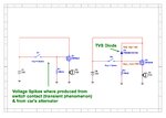
I want to on/off a P-Channel mosfet with car's ignition switch. As I know the voltage of the car when it is engaged is 14Volt and contains voltage spikes mostly of the alternator basically. After a search on the internet i found that a way to protect the gate of the mosfet is to add a TVS diode parallel to gate-source. Does anyone know if this solution is suitable in order to cut all the voltage spikes from the mosfet's gate (overvoltage on gate can destroy/puncture the thin oxide of the gate)?

The TVS "P6SMB18AT3G" according to the datasheet have "Response Time is Typically < 1 ns". Is this TVS suitable from the aspect of time?
Is this TVS suitable from the aspect of Vbr=18V or it would be better if I put a TVS with vbr=16V?

P6SMB18AT3G:
https://www.mouser.com/ds/2/308/P6SMB6.8AT3-D-99834.pdf
Design1.jpg
 

Hi, I couldn't say for sure, but TI and other manufacturer's application notes show zeners (either one at e.g. 18V or better three in series of 6V to reduce PD) used to protect Mosfet gates from spikes and overvoltages, so it evidently is tried and tested. Looking at the IRF9540 datasheet, it looks considerably slower than 1nS and you'd hope a TVS were designed to "get there first".
I'd go with the 16V one.
 

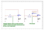
It's worth pointing out that you should also have a resistor from the gate to source or gate to ground, otherwise the gate is left floating when the switch is opened.

Also, using normal battery symbology, you have the positive at the top so the diode in the MOSFET will conduct all the time!

Brian.
 

Thanks d123 and betwixt (I have added a resistor and I have changed the mosfet polarity). Is there anyone that has practical experience with mosfet's protection gate, in order to tell me, if it is better with TVS diode or with zener diode and with which characteristics (vbr and response time)? As I saw on the internet the TVS diodes are faster than zener diodes can and withstand more dissipated power (is it write that?).

Corrected design:
Design1.jpg
 
Last edited:

TVS are better than Zeners in this application for the reasons you gave but there is probably a cheaper solution: connect a resistor (suggest 1K) in series with the gate pin, close to the MOSFET and add a capacitor of say 1uF between the gate and source (or ground). It will filter rapid changes in voltage such as the spikes but the time delay it creates in the MOSFET turnng on and off will still be insignificant.

Brian.
 

Hi again,

I think it depends on the application more than anything else, I have the attitude that Zeners belong in the 1950's and waste a lot of energy, but that's a somewhat ignorant and unscientific appraisal to say the least.

This thread discusses the two devices a little:

https://www.edaboard.com/threads/260120/

And these three pdfs could be helpful, one has very little in it, the On Semi one is a good read if you can spare that much time.
 

Attachments

  • MicroNote134.pdf
    128.1 KB · Views: 116
  • TVS-Zener Theory and Design Considerations HBD854-D OnSemi p119.pdf
    1.1 MB · Views: 81
  • Transient_Voltage_Suppression_Diode_Application_Notes.pdf
    255.2 KB · Views: 86

This thread discusses the two devices a little:

https://www.edaboard.com/threads/260120/
And as I mentioned back then, a TVS isn't just a fancy zener. A TVS really shouldn't be used unless you really expect to absorb very high energy pulses. Also some TVS devices behave like diacs in that when driven past a certain point they enter a low voltage "crowbar" state, which I don't think is desirable for gate protection circuits.

A simple zener diode with a small series resistor and maybe some capacitance will be perfectly adequate. Trying to use a TVS is asking for surprises.
 

and add a capacitor of say 1uF between the gate and source (or ground). It will filter rapid changes in voltage such as the spikes but the time delay it creates in the MOSFET turnng on and off will still be insignificant.
Shouldn't the capacitor be placed on the power supply side to filter the power supply because when the switch is OFF the capacitor is discharged... Or in this case is indifferent ?
 

Status
Not open for further replies.

Similar threads

Part and Inventory Search

Welcome to EDABoard.com

Sponsor

Back
Top