Continue to Site

Welcome to EDAboard.com

Welcome to our site! EDAboard.com is an international Electronics Discussion Forum focused on EDA software, circuits, schematics, books, theory, papers, asic, pld, 8051, DSP, Network, RF, Analog Design, PCB, Service Manuals... and a whole lot more! To participate you need to register. Registration is free. Click here to register now.

Issue in self designed continuity checker

Status
Not open for further replies.

sathiyanarayananL

Newbie level 6
Joined
Jan 9, 2016
Messages
14
Helped
0
Reputation
0
Reaction score
0
Trophy points
1
Activity points
122
Hi guys,

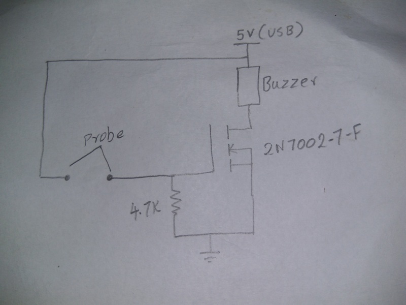
Im trying to make a continuity tester as an alternate for multimeter continuity tester. Im facing a issue, that it shows a short circuit in all conditions. The schematics for the tester have been attached.
i have powered the circuit from USB ( +5V ). Is my circuit correct?
 

Cant see your circuit / not attached


hi , plese refer to this attached schematic, sry for inconvenience
 
Last edited by a moderator:

Hi,

that it shows a short circuit in all conditions
What does this mean?

I see "probe" in your schematic.
* You mean in either case - "probe" closed or open - the buzzer is active?

Klaus
 

here on my repository you can get ideas for making yourself a continuity/low ohm meter
**broken link removed**
 

hi KlausST,

short circuit i meant was , it shows continuity always when i probe in my test board, whereas the branded multimeter in continuity mode didnt show any continuity. the probe i mentioned in the diagram is where i soldered the multimeter probe for testing boards.

thanks

- - - Updated - - -

hi crutschow,
The buzzer i have used is 5V piezoelectric type which i purchased in local market.

thanks,
 

This is a high impedance setup and even small leakage can show up as a short. Perhaps you need to clean the PCB very thoroughly.
 

Hi,

This is a high impedance setup
You need about 400uA (or more) to activate the buzzer....or a "probe_resistance" of less than 7kOhms.

But you need to know the
* "good value" and the
* "fail value" of your probe resistance.

Then adjust your resistor value on that.

Klaus
 

Your circuit is a little bit "too simple". However if you want to try to make it working, take into account that your MOS has a threshold of about 2V.
Calling Rprobe the probed resistance and R2 the resistor toward the ground you will have:

Vgate = R2/(Rprobe+R2)*Vcc that is:

Vgate = 4700/(Rprobe+4700)*5, then the threshold of 2V will be reached when Rprobe <= 7050 ohm.

If you add a resistor in series with the probe (i.e. from Vcc to the probe), let's call it R1, you will have:

Vgate = 4700/(R1+Rprobe+4700)*5

so you will reach 2V on the gate when R1+Rprobe = 7050 ohm.

If, for instance, you define "short" a resistance less than 100 ohm you need to insert R1 = 7050-100 = 6950 ohm

However the value of 2V is typical, so different transistors will have different thresholds, furthermore the threshold is temperature dependant. However you can try with R1=6.9 k and see what happen.
I suggest to put a capacitance of some hundred of pF between the gate and ground to prevent false positive due to noise.
 
hi albbg,

thanks for your input, have tested as you said, on the introduction of 6.8k in series to the probe the threshold voltage have set to 2v. but i still hear a low volume of buzzer when checking continuity across capacitors. also have noticed on powered up the circuit i see 1v in gate of the mosfet. is this condition says my mosfet is damaged??

thanks
 

Status
Not open for further replies.

Similar threads

Part and Inventory Search

Welcome to EDABoard.com

Sponsor

Back
Top