Enzy
Advanced Member level 1
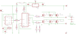
I was going through google and decided to start doing some inverter designs, a while back I ran a simulation on this circuit which seemed to work fine but what I did here is to add 2 more pairs of FETs I am not sure if I should have added individual gate resistors for each FET or its ok the way I did it.
I want to use this as a starting also I wish to add features to it like protection features ect.
how does it look so far ( I saw this design from a guy named John parfrey) just planning to modify.
I want to use this as a starting also I wish to add features to it like protection features ect.
how does it look so far ( I saw this design from a guy named John parfrey) just planning to modify.