Continue to Site

Welcome to EDAboard.com

Welcome to our site! EDAboard.com is an international Electronics Discussion Forum focused on EDA software, circuits, schematics, books, theory, papers, asic, pld, 8051, DSP, Network, RF, Analog Design, PCB, Service Manuals... and a whole lot more! To participate you need to register. Registration is free. Click here to register now.

Choosing BJT transistors

Status
Not open for further replies.

BrunoARG

Full Member level 4
Joined
Aug 15, 2014
Messages
214
Helped
38
Reputation
76
Reaction score
38
Trophy points
28
Location
Buenos Aires, Argentina
Activity points
2,177
Hello guys, I need some help with transistors.

I need to find an addecuate model for my application. It has to be cheap and wide available (I mean, if it can be a well known model (such as 2n3904 for general use) it would be better.

What I am looking for is fast transistors. I don't need UHF transistors but what I am working on is in that uncomfortable transition region where it is not low frequency nor high frequency... Do I explain myself? It will work from few Hz to 1MHz (where it starts to get trouble) and I am looking to reach at least 5 or 10MHz. I have seen people working with higher frequencies so I think it is possible and affordable.

I simulated with LTSpice a common emitter at Av=5 with 2n3904,2n2222,bc547, etc. General use transistors.
The cutoff frequency was 1MHz (-3dB). I got some minimal variations between these models.
Then I simulated a cascode with 2n2222 (which has to had a higher bandwidth, theorically) and I got the same response.

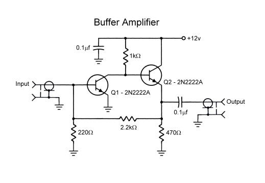
I need to make an amplifier with Av=10 as maximum, for that 5 or 10MHz frequency.

What models would you recommend me to try? What datasheet characteristics should I take into account?

Supply is +-12v and current doesn't exceed 50mA in any transistor.

Hope you can help me, I would be thankful.


______________________________________________
EDIT:

I found these:

https://pira.cz/pdf/2N3866A.pdf

https://www.fairchildsemi.com/datasheets/MM/MMBT5551.pdf

I would also need the complementary PNPs, which I can't seem to get where I live. I had to try ordering from ebay or aliexpress.
 
Last edited:

None transistor has so large Band-width so that you reach 10 MHz without loosing gain. You need negative feedback to enlarge Band-Width but still maintain gain=10 which is pretty affordable.
Did you thought of OP amps or you can not use them because of design constraints ?

- - - Updated - - -

For those in your simulation with Av=5 and BW=? (cutoff frequency is not the BW...)

Thank you for your inmediate response.

I know gain will decrease proportionally with the frequency at a point, and as current gain will vary with temperature and other factors I have to use the negative feedback, as far as I know my circuit has, indeed.

I thought about CA3086 (NPN array) and it got very high transition frequency (450MHz typ) and I can buy it here, but I don't know if it will work.

Actually I have not any design restriction, the only one is the pieces availability because if I can't get them they won't be useful. I was searching in some local vendors and I found: LM318, LM833, NE5532. A few time ago I worked with LM318 and it was pretty oscillating, but it's not a problem since it has compensation inputs.

Their characteristics:
LM318 --> PGB=15MHz, SR=50V/us
NE5532 -.> PGB=10MHz, SR=9V/us
LM338 --> PGB=15MHz (10 minimum), SR = 7V/us.

I could cascade few amplifying stages but that would increase the cost. But if it's the only way... no problem.

Anyway, I think it would be cheaper to implement a transistor amplifier (I had to try CA3086 performance).

All that was to the amplifiers.

Another important (and the overall limiter) is an output stage working as a voltage attenuator made from a variable low frequency (even DC) current mirror feeding and a NPN differential amplifier. The output must be groun referenced so I will need to make a difference amplifier out of OP amps (in lack of PNP fast transistors). Will a high speed op amp work? I mean, using external (no chip integrated silicon trimmed and thermal matched) resistors.

Thank you for your time. Hope you understand.
 

A high frequency amplifier needs plenty of current in the transistors so that the output impedance is low then stray capacitance will not cut the high frequencies. Little transistors cannot do that because they get too hot. Use larger transistors like the old 2N2219 or the BD135, BD137 and BD139 NPNs and the BD136, BD138 and BD140 PNPs.

Years ago when I worked with teleconferencing I made video amplifiers using triple video amplifier ICs.
 

I know gain will decrease proportionally with the frequency at a point, and as current gain will vary with temperature and other factors I have to use the negative feedback, as far as I know my circuit has, indeed.
What you have said , of course is necessary.

However, if I understood well, in a common emitter amplifier (Class A), there is no feedback in AC. Anyway, it is well possible (of course) to achieve what you want, but you need to design carefully for AC gain (frequency response) (even without negative feedback).
Try first with this one and transistors adviced by Audioguru, and if not, use OP amp...

- - - Updated - - -

Adjust Mid Band voltage gain and the high frequency of 3dB.
 

What a useful information.

So if output impedance is low (decreasing resistance and increasing current) then the CB capacitance won't affect as much.. it makes sense, even all RF transistor I read about is in TO-18 or similar power package. And what about input capacitance? Should I decerease the small signal output resistance so C B-E don't filter high frequencies?

Well, I search "transistor video amplifier" and all I see is low value resistors, BD family transistors and high speed op amps. I found a "7MHz amplifier" out of 2n2222a (to-18):


[from faculty . frostburg . edu/phys/latta/ee/vfo/bufferschematic.jpg]

I will try increasing currents, then... and see how much my low power transistors can give before they burn.

The other thing I keep having trouble with is this circuit:

**broken link removed**

It works perfectly well (not in LTSpice, in PCB) at about 600KHz (amplifying a triangle wave). Then it starts to filter since the triangle wave gets "shaped" and phased.

I have built the separate current mirrors before and they worked pretty well till about 6MHz, and maybe further more because I didn't try them above that. Then I think the problem is the differential amplifier... Am I right? I could upload the scope waveform but it is just that... attenuation.

This current mirror output stage is to sum the right differential output with the INVERTED (you can see the P current mirror straight feeding the N) left one. As I said, it works perfectly well but then it starts to filter.
 
Last edited by a moderator:

Sorry about the image problems.

I will upload it again

vca.jpg

Could not edit the original reply.
 

Well, I kept trying and the results I got are the following:

-UNITY gain amplifier (TL082 as buffer): The output signal is very distorted (without load at the op amp output, it would have been a good idea to load 1K ohm at least), directly measuring its output with the scope (1Meg // 13pF).

-Differential amplifier (last post) with difference amplifier (op amp) and 220 resistors between +V and collectors: The op amp I used is TL081 (4MHz PGB) and it worked very well. It started to filter from 600KHz, which is pretty poor since it should work upto 1MHz at least. Again, the output has not any load, just the scope.

-Diffetential amplifier (last post): It worked till 1MHz and then it started to distort.

NOTE: I measured the one differential amplifier collector and the shape is the same than in the input, so it is not the frequency limiter element... it is the output difference amplifier.

I will buy some LM833 to see if it can reach at least 1 or 2MHz.
 

The audio opamps you talk about work poorly at the radio frequencies you want, especially when the waveform has the harmonics of a triangle wave.
Most opamps can drive a load as low as 2k ohms but a few can drive 600 ohms. Any opamp works fine with a high resistance load.
 

Thank you for your reply.

I made some research recently, just searching "transistor RF amplifier" or "transistor high speed amplifier" and I found this interesing circuit.

In order to what the author says, it can reach 20MHz (with Av=2,6). If that's correct, I would be satisfied... Av=5 and bandwidth of 10MHz is worth to me. Actually I've seen a lot of high speed amplifiers (video and RF too) out of 2n390x, so they might have the necessary requirements.

Do you think it could work? I simulated it and its response is flat till 3MHz, then it has a peak and a falling at 45MHz. I think I can modify and try values till I get a good one.

Anyway, I will tell you what I get as I build and test it.

Any suggestion is welcome.
 

As already said, you need to think in terms of gain/bandwidth product to achieve your required performance.

But just using some kind of "super" transistor is not really the answer either, because the gain will still fall steadily with frequency where very wide bandwidth is required.
The solution is to use negative feedback to reduce and therefore control the overall gain over the required bandwidth.

That usually requires more than one transistor, but it is then possible to keep the gain fairly flat up to some usefully high frequency.
What you end up needing depends on the required gain, the maximum frequency, the output voltage swing, the type of load being driven, and the available supply voltage.

It may be a lot easier to use a suitable op amp than a bunch of discrete transistors.

You can now buy MMICs (monolithic microwave integrated circuits) with essentially fairly flat gain from dc to 6 Ghz. That may not be what you need, but there are a lot of ICs out there that can do some pretty amazing things.

Thank you, Tony.
I don't think I could buy these MMIC where I live... perhaps if I find it available, it will be very very expensive (don't know the actual price but think like if it was 10 times more expensive) they seem to be very very useful, indeed.

If you can spin that wheel to the post #11 you will find a circuit. IS NOT THAT A OP AMP? I mean, it's the same topology... differential - common collector and is backfed to force the differential stage to properly amplify the signal. If this guy could make it work at 20MHz... why my old and compact, thermal matched TL081 will not work? they are both the same thing... if smaller, lower capacitance and propagation errors. Please, could anyone explain me this?

I made some tests and measurements and I got the following:

2n3904 common emitter amplifier, ICq=54mA, VCC-VEE=24V:

**broken link removed**
(a very good inprovement from the ICq=20mA I was using). It can be seen that the distortion is pretty low, at ICq=20mA the same happened at 1MHz frequency.

**broken link removed**
Here is a very visible crossover distortion. It is coming from the wrong biased class AB buffer, the previous stage. Anyway, the higher voltage signal is very well amplified.

**broken link removed**
Here is the TL081 buffer output... pretty well at 1MHz, but not as good as the common emitter at that frequency.

**broken link removed**
And finally the same TL081 at 2.4MHz... Very bad, you can even see the phase, it definetly has reached its cutoff frequency.
 

Yes you can build something like that and it should work very well with discrete components.
Careful selection of a suitable op amp to do it would be my choice.
 

one can also use CMOS IC's with negative feedback with linear gain open loop of 1000 for buffered inverters.
I've used these in the early 70's for many non-critical 10MHz linear applications.

Now you can choose faster IC's in 5V logic with 50 ohm internal RdsOn or use discrete MOSFETs.

https://www.fairchildsemi.com/application-notes/AN/AN-88.pdf

It shows a non linear transfer, but it says it is linear... what is it?

Do you think it will work with a 10Vpp output swing at 10MHz? I read it could work at 50M but din't find the output voltage it would work with.


Tony, so you say that if I build that discrete op amp I would get better frequency response?
 

Tony, so you say that if I build that discrete op amp I would get better frequency response?
Certainly better than a single transistor amplifier.

You require 10v p/p at 10 Mhz linear amplifier, but driving what kind of load ?
 

Tony, actually the load is variable, but the voltage amplifier stage would drive a current amplifier (class AB buffer) so the load is its input impedance... around 10K.

I realised I put 10Vpp but it is 20Vpp (or 10Vpeak). It is for a function generator. Yes I know there are 40MHz DDS and analog ICs but I am building a full analog one as I saw these integrated circuits generate pretty high distortion.
 

If I were doing this myself, I might start looking on the internet for service manuals for good quality but fairly old function generators.
The performance specs for the instrument should pretty much tell yo what the output stage is capable of.
At the very least it should give you some ideas.
 

Hello, thank you for your answer.

I kept trying with the 2n3904 common emitter amplifier and I got it working!

Simulating the bode plot response in LTSpice I figured out that the input signal OUTPUT resistance does matter. If it's larger than 1K the cutoff (-3dB) is at the very 6MHz. But if the output resistance is smaller than 200 ohms it can reach 20MHz. The gain is 20dB for both of them.

. May I tell you a secret? You can add some capacitive feedback in parallel to the emitter resistor, it will compensate the gain decay at high frequencies.

So thrilled with my simulation results, I had to test it... so I did:


FFT, the exponential amplitude decay of the armonics. Showing DC because it actually has.

Triangle wave


Square wave:


NOTE: The yellow trace (CH1) is from a inverter gate (both connected to make a non inverting one) and had to have an additional propagation delay, that's why the output doesn't seem to be inverted and has pretty much delay.
The signal measured was attenuated to avoid clipping.


The only problem now is... the transistor is dissipating about 500mW. Here it is about 24ºC now and when I turn it on, I see a slow variation of the Q point till it gets the maximum temperature. That's not good because in a few months it will be 35ºC and it won't work the same, or not?
 
Last edited by a moderator:

Status
Not open for further replies.

Similar threads

Part and Inventory Search

Welcome to EDABoard.com

Sponsor

Back
Top