Continue to Site

Welcome to EDAboard.com

Welcome to our site! EDAboard.com is an international Electronics Discussion Forum focused on EDA software, circuits, schematics, books, theory, papers, asic, pld, 8051, DSP, Network, RF, Analog Design, PCB, Service Manuals... and a whole lot more! To participate you need to register. Registration is free. Click here to register now.

[SOLVED] How to implement back to back silicon diodes in the negative feeback path of an opamp

Status
Not open for further replies.

Tahirmis_ic

Junior Member level 1
Joined
Feb 16, 2016
Messages
15
Helped
0
Reputation
0
Reaction score
0
Trophy points
1
Activity points
192
Hi all,

The question is about the soft clipping stage of an oscillator integrated circuit designed with Cadence Virtuoso. The technology used is CMOS and the process is AMS 0.35um.

I want to design a back to back silicon diodes in the negative feeback path of an op-amp in CMOS technology. The process design kit used offers a lateral bjt and vertical bjt as pn junctions solution.

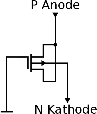
In the case of vertical bjt (Emitter P+, Base Nwell, Collector PSub), the fact that diodes are in the feedback path of my op-amp doesn't allow to connect Base to Collector, since collector is connected to Substrat. Is it right (Nwell Psub process) ?

My lateral bjt transitor consists of a vertical and a lateral part. Emitter and Collector are separated by the gate. How to connect the gate? to Base ? Is the lateral bjt a better solution than the vertical bjt to implement my back to back silicon signal diodes? Why?

I think we can't implement the back to back diode behavior with mosfets connected as a diode in the case of negative feeback path of an op-amp . It is right?
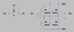
Because I am using Nwell Psub process. In the case of the pmosfet transistor, bulk is Nwell and it is connected to the higher voltage in the circuit, but I can connect it to a level less than Vdd because we have several nwells and we mustnt connect them to common voltage, so they could be connected to different voltages. In the case of nmos, the bulk is Psub, and I should connect it to Vss (knowing that there is only one substrat, it is right?). This why I said that implementing a back to back silicon diodes in the negative feeback path of an op-amp in CMOS technology is not allowed whith the mosfet configured as diode with the process used. Am I right?

I want to know if there are others possibilities than using paratic pnp to implement a back to back diodes in cmos technology with Nwell Psub process ? Actualy I use the Base Emitter junction and I connect Collector to VSS because The process used doesn't allow me to connect in a other way.


Thanks all,
 

Maybe you want to use source-follower MOSFETs instead.
In a JI process your diode choices are few, and fewer still
if you want both terminals not-tied-to-substrate or being
half of a parasitic BJT.
 

In "theory" You could use pmosfet to it. By shorts a drain and source together and biasing it with high enough Vgs to create a channel, You will have a pn junction between a channel and nwell. So your diode electrode will be bulk - a anode, and S/D as a cathode. The gate should be grounded than.

But I suppose that it is a simpler and more common way to realize your circuit in CMOS process.
In literature is a number of papers about logarithmic amplifiers and multipliers also. Check them.
 

I think, a pmosfet not only works in theory, but also quite practically: with its individual nwell (connected to the source) you are free to choose its potential level. Connect the gate to the drain to use it in diode-connection configuration, which guarantees a "forward voltage" of about the threshold voltage. Its anti-parallel parasitic drain-to-nwell p+n junction represents the back-to-back diode, with a forward voltage of 0.6 .. 0.7V .
 
  • Like
Reactions: CataM

    CataM

    Points: 2
    Helpful Answer Positive Rating
I said that the pmosfet solution doesn't work in CMOS Nwell Psub process because :

- the desired junction is p+(drain)- Nwell, knowing that diodes are in the feedback of the AO-amp, in the case of diode "1" with Vp connected to Vout and Vn connected to virtual ground (INN of AOPAMP), the Vp(diode1)=Vout, as we want the diode to work in forward, Vp=Vout > Vn. In this case, we have a bjt, since the psub is connected to VSSA and so Base-collector(sub) junction is reversed biased and the B-E junction is in forward.

I think that we can't design a feedback diode in cmos Nwell Psub process , because if we use pmosfet or parasitic vertical bjt, it is the same thing since we use p+ (Drain )
Nwell junction in forward and the fact that Substrate is always connected to VSSA (we have the base collector-sub junction reversed biased), it results in a pnp bjt with a considerable value of collector(substrate) current. Am I right?

Any anothers suggestions?
 

Read again my post. It is possible to use a p-n junction made by pmos channel and its nwell. Substrate is not consider in this case.
But question is, for what purpose You need diode in opamp feedback? If for logarithmic amplifier, there are number of pure cmos solutions for it.
 

A sketch of source-follower cross-clamp which may suit
the application. Difference from simple unencumbered
diodes is, any overtravel current is returned to the supply
(whichever) and not across the clamp to the other side.

All majority-carrier, no storage time, may be a significant
advantage in higher speed circuits.
 

Attachments

  • B2Bdiodes.png
    B2Bdiodes.png
    19.4 KB · Views: 99

Read again my post. It is possible to use a p-n junction made by pmos channel and its nwell. Substrate is not consider in this case.
But question is, for what purpose You need diode in opamp feedback? If for logarithmic amplifier, there are number of pure cmos solutions for it.

Hi Dominick, I want to use it for a soft-clipping amplifier with two back to back diodes in the negative feedback path of an amplifier in parallel with a resistance, the function of the circuit is limiter/compressor to have the loop gain superior then equals to unity in absolute magnitude.
I don't understand your answer because I don't know how to connect the channel to the output and input of opamp to make a back to back diode. Also, I don't know how to have a high VGS to create the p-channel and the gate grounded in the same time. miss I something? Can you please draw a schematic to allow me understand your solution?
Do you think that a log-amplifier could be a better solution to design a soft-clipping amplifier?
thank you
 

Hi dick_freebird, It looks a good solution for my soft limiter. I googled source-follower cross-clamp but I don't find more information about it. Can you please give some references (papers or books...) about it? Thanks a lot,
 

I thought about connection as in attached picture. The VGS will be equal to signal common mode if You place this structure into opamp feedback (I suppose half of vdd).
The logarithmic amplifier was a first thing which I was thinking during read your post. So if You need soft clipper, I know that there are a few patents how to implement this kind of circuit in pure cmos without any p-n junction. There should be also a number of articles with some well-working ideas (google scholar showing a 15k of results)


pmoschanel_diode_sim_testbench.pngpmoschanel_simu_diode_results.pngppnp_diode_sim_testbench.pngpnp_simu_diode_results.png

Hi Dominik,
I simulated the solution with pchannel-nwell junction (please see attached pmoschannel_simu_diode_results and pmoschannel_sim_testbench), I explain the results as follows, the source and the drain ohmic contact behave like two diodes with the Nwell, and the sum of the two currents of the two diodes equals to the result current at the output (MP0/bulk). But, in this case I don't simulate the substrate effect because at the moment I don't know how to simulate this effect. I continue to think that the bjt problem exists because in the cross section , we always have p(drain/source/channel)-Nwell-Psub with p(drain/source/channel)-Nwell in forward and Nwell-Psub in reverse. Can I know why do you say "that substrate is not consider in this case"?. I think substrate must be considered since Nwells share a common substrate.

I also join ( pnp_simu_diode_results and ppnp_diode_sim_testbench.png) to illustrate the collector current due to the common substrate.

thanks,
 

Can I know why do you say "that substrate is not consider in this case"?. I think substrate must be considered since Nwells share a common substrate.
Because as long as a substrate is connected to the lowest supply voltage, the diode formed by any nwell and a substrate is always reverse biased.
 

Sure, but the same is true of a PNP BJT - collector
reverse biased but substantial gain and current flow.
You -will- be injecting current to the NWell (base) if
the P+/NW diode is forward biased. What is the result
of that, depends on the circuit and the device details
(Rb, hFE vs Ic and vs Ib, and so on).

Answer being, to make your own macromodel (or add
a realistic PDK device library element) properly hooked
up, and see what difference it makes.

I've seen people get bitten by the "diode is really a BJT"
thing before. It may not be a good one, it may not be
helpful, but there's no getting away from it other than
SOI (and even there, you do have a BJT under every
MOSFET; however you are at liberty to make an actual
PN-and-nothing-but structure in SOI). But that has not
been on the table thus far.
 
Because as long as a substrate is connected to the lowest supply voltage, the diode formed by any nwell and a substrate is always reverse biased.
I am agree with you, i.e, as the substrate is always connected to the lowest supply voltage (because there is only one and common substrate in the circuit), we always must connect it to the lowest supply to make the diode Psub-Nwell in reverse.
Why do we want to reverse the Nwell-Psub junction? Because we don't want to have current from nwell through psub .
And, as we have several nwells, we can connect nwells to another voltage than Vdd. But, one conditition, we must not have the p(drain/source)-Nwell junction in forward.
Why connecting the nwell to vdd is the best choice? Because, by connecting it to vdd, we can't have the p(drain/source)-Nwell junction in forward. And why don't we want to have the p(source/drain)-Nwell junction in forward? Because, as the N-well-Psub junction is in reverse, by having the p(source/drain)-Nwell junction in forward, it results a parasitic pnp, i.e p(source/drain/pchannel)-Nwell-Psub).
And, why the pnp is not wanted? because of the considerable value of the current in substrate (ic=beta*ib, ib is the current of p(source/drain/pchannel)-nwell junction and ic is the current of p(source/drain/pchannel)-psub)
Am I right by saying this or I miss something? Please revise this justification and feedback!

- - - Updated - - -

I thought about connection as in attached picture. The VGS will be equal to signal common mode if You place this structure into opamp feedback (I suppose half of vdd).
The logarithmic amplifier was a first thing which I was thinking during read your post. So if You need soft clipper, I know that there are a few patents how to implement this kind of circuit in pure cmos without any p-n junction. There should be also a number of articles with some well-working ideas (google scholar showing a 15k of results)


Hi Dominik,

I hard searched a publication (patent or article on google scholar and ieee xplore) about how to implement a soft clipping circuit in pure cmos without any p-n junction but I don't find anything. Can you please give me some references ?

thank you,
 

Status
Not open for further replies.

Part and Inventory Search

Welcome to EDABoard.com

Sponsor

Back
Top