Continue to Site

Welcome to EDAboard.com

Welcome to our site! EDAboard.com is an international Electronics Discussion Forum focused on EDA software, circuits, schematics, books, theory, papers, asic, pld, 8051, DSP, Network, RF, Analog Design, PCB, Service Manuals... and a whole lot more! To participate you need to register. Registration is free. Click here to register now.

LC filter in the Sinewave Inverter

Status
Not open for further replies.

usama14

Member level 5
Joined
Oct 31, 2015
Messages
90
Helped
0
Reputation
0
Reaction score
0
Trophy points
6
Activity points
756
FYP: LC filter in the Sinewave Inverter

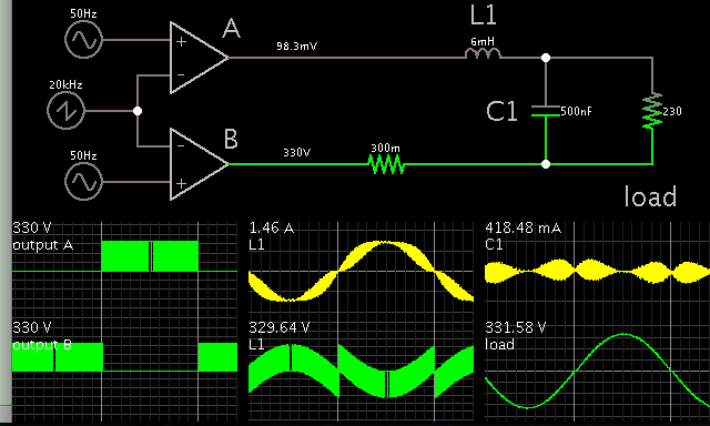
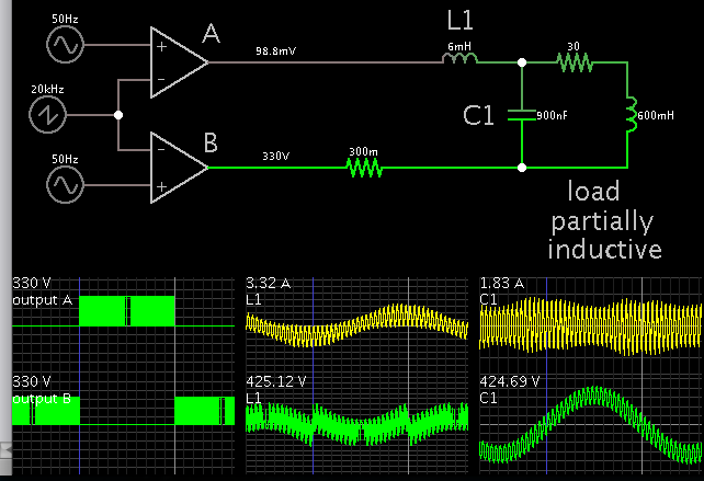
Hello All. I successfully completed the DC-DC converter stage getting 330VDC at the output (it was shortening and by increasing the duty cycle, its working now). Now the problem is coming at the output filter at the Inverter stage. The output LC filter is now making the output to go short and Im not geting anything. My carrier freq= 20kHz and L=6mH and C=tried many from nano farads to 1uF. but still hopeless.
The thing is it all worked before with C=0.5uF and same conditions :/ Kindly help, its my last day to submit FYP :/
*edit* I have actually been able to drive an AC fan with the same specs. But my circuit was damaged bcz I got an electric shock and had to rebuild it. Now Im stuck in this stage where I had already been through.
 

My condensed simulation shows your setup ought to work.

Two op amps mimic an H-bridge delivering SPWM.


My load is resistive, 1A. Your AC fan is not a resistive load. Instead it may be partially resistive and partially inductive. The inductive portion may result in a power factor problem to your H-bridge. Poor power factor has the load trying to draw peak Amperes at a point when the voltage waveform is off-peak.

Did you try a resistive load (example, incandescent lamp) on your inverter? Did you get ample output then?
 

Yes I tried the resistive load and it worked great before.
Actually everything worked fine before. With the inductive fan I got the following waveforms.
2.jpg
3.jpg
This was before it went faulty.
But Now, after making it all again, I am getting the H-bridge output at the resistor like
1.png
But when I connect the same LC for 50Hz sinewave filtration as before, my circit switches OFF. I tried very small capacitor values but nothing effective happens :(

- - - Updated - - -

My condensed simulation shows your setup ought to work.

Two op amps mimic an H-bridge delivering SPWM.


My load is resistive, 1A. Your AC fan is not a resistive load. Instead it may be partially resistive and partially inductive. The inductive portion may result in a power factor problem to your H-bridge. Poor power factor has the load trying to draw peak Amperes at a point when the voltage waveform is off-peak.

Did you try a resistive load (example, incandescent lamp) on your inverter? Did you get ample output then?

Also the output was stable before without the need of the feedback.
 

when I connect the same LC for 50Hz sinewave filtration as before, my circit switches OFF. I tried very small capacitor values but nothing effective happens :(

The inductor acts as a choke, filtering out the carrier to some extent. The capacitor has the job of filtering out the carrier as well, although it also performs power factor correction.

This simulation has a load which is partly inductive, partly resistive. It is a rough guess at simulating a fan.

Notice the Ampere waveform through the inductor is out of alignment with the voltage waveform. Your output stage is trying to draw maximum A at a time when the voltage waveform is crossing 0V. This is incompatible with the way the H-bridge is switched. (Notice that my post #2 has the Ampere and Voltage waveforms coinciding, with a resistive load.)


In addition certain LCL combinations can cause unexpected resonant action. Odd waveforms can crop up, as well as high voltages. I found that very small C values produce waveforms which climb up into the kilovolts. This may be similar to what happens with your project.

Of course my simulations are only theoretical however they point out where a problem might occur. It would help if you were to take simultaneous scope traces, current vs voltage, etc.

But why did it work in the first place then? Thats the real question isn't it?
 

But why did it work in the first place then? Thats the real question isn't it?

Evidently you did things right until this point:

my circuit was damaged bcz I got an electric shock

Did you by any chance disconnect the load? This LC filter (second order butterworth) is known for generating extreme amplitudes if it is not loaded, particularly if driven at its resonant frequency. In the role of an audio amplifier crossover, it can blow the amp if the woofer is not connected.
 

Evidently you did things right until this point:


Did you by any chance disconnect the load? This LC filter (second order butterworth) is known for generating extreme amplitudes if it is not loaded, particularly if driven at its resonant frequency. In the role of an audio amplifier crossover, it can blow the amp if the woofer is not connected.

No I didnt disconnect the load. Also, I am testing the circuit now and still the problem is persisting :(
Any more Ideas that you can share plzz?
Also, do you know how to drive H-Bridge using the HCPL-3120? :/
 

It appears you have no choice but to test all components individually. All are suspect at this point.

The inverter can be seen as a buck converter driving the load in one direction, then the other direction. Duty cycle is low-high-low, thus shaping a sinewave, first in the positive polarity, then the negative.

The H-bridge needs to be switched in a fashion that duplicates the buck converters. The LC filter needs to have values selected so you avoid resonant behavior.

Sorry, I have no hands-on experience with control IC's such as you mention.

BREAKING NEWS: I connected a resistor in series with the inductor and observed output waveform across the load and capacitor. And BOOM. Got the sinewave. Does this mean the Inductor IS GETTING SATURATED AT HIGH VOLTAGES???
If yes, then what should I do? I am using the 3C90 ETD59 core for the inductor with no gap. :/
Also, you mean to sellect values for the LC filter as for the BUCK CONVERTER?
 

BREAKING NEWS: I connected a resistor in series with the inductor and observed output waveform across the load and capacitor. And BOOM. Got the sinewave. Does this mean the Inductor IS GETTING SATURATED AT HIGH VOLTAGES???
If yes, then what should I do? I am using the 3C90 ETD59 core for the inductor with no gap. :/

A resistive load behaves in a simple manner. Often it is recommended to use a resistive load when you want to test for output power, waveforms, etc.

Apparently the inductive load creates reactive effects, resonant action at odd frequencies and odd waveforms, power factor problems, etc.

Also, you mean to sellect values for the LC filter as for the BUCK CONVERTER?

Yes, the effect is the same.

In addition you must ensure that the H-bridge is switched properly, so that the load is first grounded at the right side, while the left side performs rapid SPWM switching action. (This duplicates the action of a buck converter.)

Then ground the left side of the load, while the right side performs switching action. (This again is the action of a buck converter but in the opposite direction through the load.)
 

A resistive load behaves in a simple manner. Often it is recommended to use a resistive load when you want to test for output power, waveforms, etc.

Apparently the inductive load creates reactive effects, resonant action at odd frequencies and odd waveforms, power factor problems, etc.


Yes, the effect is the same.

In addition you must ensure that the H-bridge is switched properly, so that the load is first grounded at the right side, while the left side performs rapid SPWM switching action. (This duplicates the action of a buck converter.)

Then ground the left side of the load, while the right side performs switching action. (This again is the action of a buck converter but in the opposite direction through the load.)

You're saying that Its okay attach a resistor in series? But It is dropping hell of output voltage :/
 

Everything you try reveals some facet of behavior of your project. Fortunately you got it working again by adding a resistive load. If you wish to remove the resistor, then changing something else ought to allow your project to continue to work. (For instance, increasing the capacitor value. The high L:C ratio tends to generate high amplitude ringing oscillations. Therefore it should help if you reduce the L:C ratio.)

Remember that your project is experimental. It won't give you the same performance as a store-bought unit.
 

To be able to work with open circuit or pure reactive load, a LC outwork filter must have a certain amount of damping. It should be designed so that it doesn't cause much losses at the fundamental inverter frequency and also keeps the high frequency attenuation. A straightforward way is to add a RC series circuit in parallel to the output capacitor, dimensioned in a trade-off between low resonant Q and pwm frequent losses.

If the problem of your filter is too high Q, the solution can help. Unfortunately the observations are too vague to tell clearly what the problem is.
 

Everything you try reveals some facet of behavior of your project. Fortunately you got it working again by adding a resistive load. If you wish to remove the resistor, then changing something else ought to allow your project to continue to work. (For instance, increasing the capacitor value. The high L:C ratio tends to generate high amplitude ringing oscillations. Therefore it should help if you reduce the L:C ratio.)

Remember that your project is experimental. It won't give you the same performance as a store-bought unit.

I am currently using this combination.
13523794_497361237116105_1997505147_o.jpg
I tried increasing the "C". But the output gets shortened dur to unknown reasons :/
(Also, yesterday I couldnt get the same results either, that is, everything was shortening out when the capacitor was connected. Then dont know after 4 hours of hardwork...it started to work again. Its ALL CONFUSING :()

To be able to work with open circuit or pure reactive load, a LC outwork filter must have a certain amount of damping. It should be designed so that it doesn't cause much losses at the fundamental inverter frequency and also keeps the high frequency attenuation. A straightforward way is to add a RC series circuit in parallel to the output capacitor, dimensioned in a trade-off between low resonant Q and pwm frequent losses.

If the problem of your filter is too high Q, the solution can help. Unfortunately the observations are too vague to tell clearly what the problem is.

You mean to use this combination??
13523749_497360453782850_889089957_o.jpg
How to calculate its values? Any formulas etc? My Fs=20kHz right now and I want output to be of 50Hz.
This is the Inverter side's schematic.1.png
 
Last edited:

You mean to use this combination??
Yes.
How to calculate its values? Any formulas etc? My Fs=20kHz right now and I want output to be of 50Hz.
I don't have a formula, unfortunately. I would use 50 Hz Lpercent of one up to a few percent as a starting value, 1 to 3 kHz cut-off frequency, Q as low as possible. The capacitor with series resistor should be one to five multiple of the other. Verify in a simulation.

You didn't mention inverter output current. 6 mH might be a reasonable value.

I noticed a previous statement
I am using the 3C90 ETD59 core for the inductor with no gap.
That doesn't look right. You don't get saturation with PWM voltage but easily with output current. The choke must fulfill two conditions:
- can handle Bmax according to PWM AC voltage V seconds (core area, number of turns)
- can handle Ipeak rated output current (air gap, magnetic path length, number of turns)

A choke designed for some amount of DC or low frequent current need an air gap to fulfill the second condition
 

Yes.

I don't have a formula, unfortunately. I would use 50 Hz Lpercent of one up to a few percent as a starting value, 1 to 3 kHz cut-off frequency, Q as low as possible. The capacitor with series resistor should be one to five multiple of the other. Verify in a simulation.

You didn't mention inverter output current. 6 mH might be a reasonable value.

I noticed a previous statement

That doesn't look right. You don't get saturation with PWM voltage but easily with output current. The choke must fulfill two conditions:
- can handle Bmax according to PWM AC voltage V seconds (core area, number of turns)
- can handle Ipeak rated output current (air gap, magnetic path length, number of turns)

A choke designed for some amount of DC or low frequent current need an air gap to fulfill the second condition

Success IT IS I was successfully able to make my project working again. The problem was not of the filter or anything. It was the unproper grounding in the building I'm working at. The ground is giving a freaking 90V and I had to isolate my project from it. And it worked perfectly. :)
Now the only thing remaining is the voltage regulation for maintaining the 330VDC. Kindly throw some light upon the regulation based on the optocouplers etc, I dunno much about them. :)
Also,my last question is that I connected a pedestal fan in the load and it worked with the dc voltage coming down to 260V. My true load is a 375W submersible pump, will it drive it in the current state or not?
Thankyou.
 

My true load is a 375W submersible pump, will it drive it in the current state or not?
Thankyou.

Good going. Glad you solved it. Never heard of a building with ground at 90V. Is the wall receptacle properly wired?

It is common for an AC motor to draw a current surge at powerup. It may be several times the running value. Your inverter output will drop during the first second or two. However since the load is a propeller in water, it ought to be able to tolerate momentary low voltage. The situation might be different if the inverter needed to send a lot of power to overcome an extreme mechanical force.
 

The problem was not of the filter or anything. It was the unproper grounding in the building I'm working at. The ground is giving a freaking 90V and I had to isolate my project from it. And it worked perfectly. :).


The earth (ground) is a basic safety feature and is connected to the metal casing and never to any part of the electrical circuit. Do you suggest that your circuit will not work without a earth connection?

Are you connecting the circuit common ground points to the earth point at the plug?
 

Good going. Glad you solved it. Never heard of a building with ground at 90V. Is the wall receptacle properly wired?

It is common for an AC motor to draw a current surge at powerup. It may be several times the running value. Your inverter output will drop during the first second or two. However since the load is a propeller in water, it ought to be able to tolerate momentary low voltage. The situation might be different if the inverter needed to send a lot of power to overcome an extreme mechanical force.
Thankyou. :) Also, the inductance of the motor is 30mH. So, dont you think it will distort the waveform and drop hell of the voltag too? I am not regulating the dc dc stage right now either.

- - - Updated - - -

The earth (ground) is a basic safety feature and is connected to the metal casing and never to any part of the electrical circuit. Do you suggest that your circuit will not work without a earth connection?

Are you connecting the circuit common ground points to the earth point at the plug?

Yes, I isolated the ground point from the plug by using 2 pin connector.
 

The ground is giving a freaking 90V and I had to isolate my project from it. And it worked perfectly. :).

Ground potential is zero by definition; where did you put the other end of the multimeter probe? Perhaps the ground connection is lost (broken; disconnected)? Please check carefully.
 

Status
Not open for further replies.

Part and Inventory Search

Welcome to EDABoard.com

Sponsor

Back
Top