Continue to Site

Welcome to EDAboard.com

Welcome to our site! EDAboard.com is an international Electronics Discussion Forum focused on EDA software, circuits, schematics, books, theory, papers, asic, pld, 8051, DSP, Network, RF, Analog Design, PCB, Service Manuals... and a whole lot more! To participate you need to register. Registration is free. Click here to register now.

[SOLVED] Commercially available F/V converter or F/I converter

Status
Not open for further replies.

bhl777

Full Member level 6
Joined
Sep 30, 2008
Messages
363
Helped
0
Reputation
0
Reaction score
0
Trophy points
1,296
Activity points
5,140
Hi all, I am looking for a frequency to voltage or frequency to current converter, that can process sinusoidal signal around 1MHz. However, I searched in digi-key but did not find any suiatble commercially available ICs to meet this specs. Would anybody recommendate the places I can go to search for this kind of product? This converter is for signal level processing, and ideally I want the VCC be low as 5V or 3.3V.
Thank you!
 

Which technique you use depends on how far the frequency swings, and how fast it swings and the degree of accuracy required.

Narrow band FM is a very different thing to 0 to 1Mhz tachometer that varies slowly over hours.
 

Which technique you use depends on how far the frequency swings, and how fast it swings and the degree of accuracy required.

Narrow band FM is a very different thing to 0 to 1Mhz tachometer that varies slowly over hours.

Hi Warpspeed, I target to have the frequency swings around 500k to 1.5MHz, high precision is not required. An approximately linearity between the input frequency of the sin signal and the output voltage/current is good enough. Thank you!
 

A phased lock loop should be able to do that fairly easily.

A 74VHC4046 would do the whole thing, 3.3v and up to 12Mhz.
http://cds.linear.com/docs/en/datasheet/6990fc.pdf

If you need better accuracy, the VCO in an LTC6990 would be better than the vco in the 4046, but the phase detector in the 4046 is excellent.
http://cds.linear.com/docs/en/datasheet/6990fc.pdf

Just have the vco track the input signal, and the voltage at the vco control pin will be your output voltage.

Set the vco to sweep between 400 Khz and 1.6Mhz and you are set to go.
 

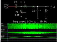
Since the input signal is a sinewave, then it could work to feed it to a high pass filter. Adjust values so you obtain a rolloff curve which is more or less linear. Then send the result to a sample-and-hold.


The diode ought to be fast recovery type.
 

A phased lock loop should be able to do that fairly easily.

A 74VHC4046 would do the whole thing, 3.3v and up to 12Mhz.
http://cds.linear.com/docs/en/datasheet/6990fc.pdf

If you need better accuracy, the VCO in an LTC6990 would be better than the vco in the 4046, but the phase detector in the 4046 is excellent.
http://cds.linear.com/docs/en/datasheet/6990fc.pdf

Just have the vco track the input signal, and the voltage at the vco control pin will be your output voltage.

Set the vco to sweep between 400 Khz and 1.6Mhz and you are set to go.

Thank you Warpspeed! An additional two questions:
(1) do I have the control to the generate voltage in using LTC6990 or 74VHC4046? For example, if I use 1MHz as the nominal frequency, can I determine the nominal VCO output voltage V1? In addition, do I have the control to the slope as well?
vco.png
(2) If I want to generate a current that is proportional to the frequency of the input signal, can it be done using LTC6990 or 74VHC4046?

- - - Updated - - -

Since the input signal is a sinewave, then it could work to feed it to a high pass filter. Adjust values so you obtain a rolloff curve which is more or less linear. Then send the result to a sample-and-hold.


The diode ought to be fast recovery type.

Hi BradtheRad, do you mean using this circuit you propose and go through a SH circuit, we can get the same results of the F/V conversion? Actually my appliation will not require high speed sweep, just need to (1) generate different voltage/currents from different input frequency, no matter what amplitude of the sinusoidal signal is (2) when frequency suddently changes, the generated output voltage can change smoothly to the steady state.
Would you advise if I can use your circuit to determine the nominal voltage V1 and the slope in the following figure? Thank you!
vco2.png
 

Standard f/V converters have frequency ranges up to 500 kHz. Add a comparator and a prescaler.

Other solution would be a 4046 or similar PLL locked to the input signal. Frequency proportional signal available at the VCO input.

Or edge-triggered monoflop (e.g. 74HC series) with low-pass filter.
 

Thank you Warpspeed! An additional two questions:
(1) do I have the control to the generate voltage in using LTC6990 or 74VHC4046? For example, if I use 1MHz as the nominal frequency, can I determine the nominal VCO output voltage V1? In addition, do I have the control to the slope as well?
You would set up the voltage controlled oscillator in the 4046 so that 0V = 400Khz and 3.3v = 1.6 Mhz (or whatever).
There are two resistors to set the upper and lower limits of the range, and both limits are independent.

Operation between those limits will be linear in voltage, or IMhz = 1.65v or very close to that. The output will be a dc voltage proportional to frequency within the range.

If you need a current source or sink, that will require voltage to current conversion, which will need to be designed to suit your requirements.
 

My circuit only works if your signal is constant amplitude. If your signal varies in amplitude then an automatic gain control may be needed.

Thank you BradtheRad. Sorry I did not mention it clearly. I was trying to say I want the output of VCO to be relatively insensitive to the variation of the amplitude. For example, the nominal peak voltage of the sinusoidal signal is 0.5V, but in some other operating conditions, it may stay in other constant levels, such as 0.1V, 0.2V, 0.3V, 0.4V, 0.6V, 0.7V, 0.8V. Will you circuit give the output voltage similar to what we get from a 0.5V peak amplitude sinusoidal signal?
 

Will you circuit give the output voltage similar to what we get from a 0.5V peak amplitude sinusoidal signal?

To drive my circuit, the signal needs to be a few volts amplitude, so it overcomes the diode threshold. Your signal needs to be conditioned by amplifying it, and level-shifting. A single transistor stage might do the job.
 
  • Like
Reactions: bhl777

    bhl777

    Points: 2
    Helpful Answer Positive Rating
You would set up the voltage controlled oscillator in the 4046 so that 0V = 400Khz and 3.3v = 1.6 Mhz (or whatever).
There are two resistors to set the upper and lower limits of the range, and both limits are independent.

Operation between those limits will be linear in voltage, or IMhz = 1.65v or very close to that. The output will be a dc voltage proportional to frequency within the range.

If you need a current source or sink, that will require voltage to current conversion, which will need to be designed to suit your requirements.

Hi Warpspeed, thank you! Will the output of the VCO in 4046 sensitive to (1) the amplitude of the input sinusoidal signal(2) Vcc and temperature?
 

The phase comparator in the 4046 is "supposed" to be biased to the mid point and can be driven directly by a capacitively coupled sine wave.
It does work, but is not really recommended practice especially if the sine wave can become very low in amplitude.

The solution to that is to place an over driven amplifier ahead of the phase detector such that the output is always a saturated clipped square wave when the input is a variable amplitude sine wave. A couple of cascaded CMOS inverter stages run at 3.3v will generate a lovely square waves with fast edges from a very low amplitude input.

Vcc and temperature effects are inescapable, but it depends on your accuracy and stability requirements.
A 4046 is probably good enough for general use, but if extreme precision is required, a dedicated higher performance vco may be worth further consideration.

In fact, if you expect high quality precision instrument performance, an entirely different F to V technique altogether may be more appropriate.
 
  • Like
Reactions: bhl777

    bhl777

    Points: 2
    Helpful Answer Positive Rating
Hi Warpspeed, I tried your solution in my Simetrix simulation, but there must be something wrong with my connection, thus I cannot get the correct results.

As you can see in this schematic, I have
(1) a 1V amplitude sine wave, with 0 offset and 800kHz frequency to go to the VCOin;
(2) the central frequency is set to 1MHz by R1 and C1, and leave R2 open.
(3) The VCC is 3.3V of the PLL, with all other pins unconnected
VCO question.png

However, the VCOout is a digital waveform,not an analog DC voltage. I still do not fully understand how to use VCO to achieve the frequency to voltage conversion. Would you advise me what is wrong in my circuit configuration?

Thank you!


The phase comparator in the 4046 is "supposed" to be biased to the mid point and can be driven directly by a capacitively coupled sine wave.
It does work, but is not really recommended practice especially if the sine wave can become very low in amplitude.

The solution to that is to place an over driven amplifier ahead of the phase detector such that the output is always a saturated clipped square wave when the input is a variable amplitude sine wave. A couple of cascaded CMOS inverter stages run at 3.3v will generate a lovely square waves with fast edges from a very low amplitude input.

Vcc and temperature effects are inescapable, but it depends on your accuracy and stability requirements.
A 4046 is probably good enough for general use, but if extreme precision is required, a dedicated higher performance vco may be worth further consideration.

In fact, if you expect high quality precision instrument performance, an entirely different F to V technique altogether may be more appropriate.
 

First just test the VCO part, the circuit should look like this:

VCO Circuit.png

The two resistors set the upper and lower frequency limits.
Pin 11 high frequency limit
pin 12 low frequency limit.
The capacitor between pins 6 and 7 controls the general overall frequency range.

Find values for all three components experimentally, so that the 100K potentiometer when adjusted varies the VCO output frequency on pin 4 from something well below 500Khz to something well above 1.5 Mhz.

Get that part working first.
 

Hi Warpspeed, thank you for your advise! I followed your connection and have VCO works. Right now my output is like this:
VCO2.jpg

As my understanding from your statement "the 100K potentiometer when adjusted varies the VCO output frequency on pin 4 from something well below 500Khz to something well above 1.5 Mhz", it looks like a voltage to frequency conversion. However, what I want is a frequency to voltage conversion, which outputs an analog DC voltage which is proportional to the input frequency. Do I misunderstand your comments? Or I should do some postprocess to achive my frequency to voltage conversion? An example of my target conversion can be :
frequency of input sin signal: 800k-->Vout =1.5V
frequency of input sin signal: 1000k-->Vout =2.5V
frequency of input sin signal: 1200k-->Vout =3.5V

Thank you!
First just test the VCO part, the circuit should look like this:

View attachment 131597

The two resistors set the upper and lower frequency limits.
Pin 11 high frequency limit
pin 12 low frequency limit.
The capacitor between pins 6 and 7 controls the general overall frequency range.

Find values for all three components experimentally, so that the 100K potentiometer when adjusted varies the VCO output frequency on pin 4 from something well below 500Khz to something well above 1.5 Mhz.

Get that part working first.
 

I know what you want, but getting the VCO to work over the required range of operating frequency is just the very first step.

Once that is working properly, the VCO is phase locked to the incoming frequency.

When it is properly phase locked the voltage driving the VCO will be your dc output voltage that changes with the incoming frequency.

If you want to have 1v dc output at 500 Khz, you need to tweak the VCO to run at 500 Khz with one volt dc input, set on the potentiometer.

If you want to have (say for example) 4.75 volts output at 1.5 MHZ, you must tweak the VCO to produce 1.5 Mhz output with the potentiometer set to 4.75 volts.

This all needs to be set up BEFORE you close the feedback control loop, otherwise its not going to have any chance of phase locking.
 

Hi Warpspeed, thank you so much for your advise! Now I am much clear on your smart idea.
I twick R and C, to have a 1MHz square wave at VCo_Out, when VCO_in is 1.2V. I guess this is what we need before close the loop.
VCO3.JPG
However, when I tried to close the loop using PC1out, with a 1k and 1u RC filter, VCO_in goes to 2.5V, not 1.2V as I want. Would you tell me what is wrong with my connection?
VCO4.JPG
Thank you!


I know what you want, but getting the VCO to work over the required range of operating frequency is just the very first step.

Once that is working properly, the VCO is phase locked to the incoming frequency.

When it is properly phase locked the voltage driving the VCO will be your dc output voltage that changes with the incoming frequency.

If you want to have 1v dc output at 500 Khz, you need to tweak the VCO to run at 500 Khz with one volt dc input, set on the potentiometer.

If you want to have (say for example) 4.75 volts output at 1.5 MHZ, you must tweak the VCO to produce 1.5 Mhz output with the potentiometer set to 4.75 volts.

This all needs to be set up BEFORE you close the feedback control loop, otherwise its not going to have any chance of phase locking.
 
Last edited:

First make sure the VCO gives the correct frequencies at the correct dc input voltages as below:
frequency of input sin signal: 800k-->Vout =1.5V
frequency of input sin signal: 1000k-->Vout =2.5V
frequency of input sin signal: 1200k-->Vout =3.5V
If that is all correct, and your phase detector is correctly hooked up, you can then work on the loop filter time constant and damping.

If your output voltage is at 2.5v, it sounds very much like it is not locking for some reason.

Here is a link to a circuit and component calculator:
https://www.changpuak.ch/electronics/calc_03.php
 
Last edited:

Hi Warpspeed, I can make it sort of work now. I was using PC1out and got 2.5V, and as you said it is likely not locking.
I changed the connection to PC2out, now I can get it work at 5V vcc (strangly 3.3V Vcc cannot make it work).
This is how it looks like. It is very close to my original target. I appreciate for your kindest help.
VCO5.JPG
Right now my questions are mainly about the output of the source follower, the DEMODout. My target is to use the generated DC voltage as an input reference signal to the other building blocks, such as the LDO.
(1) As you can see, without any connection, it has a negative -10V. Is it a correct voltage level? If not, how should I correct it?
(2) If the output of DEMODout is not correct, should I say the correct one is a volatge level slightly less than VCOin? That means VCOin goes into a level shifter and get a low impedance signal out at DEMODout.
(3) If the correct DEMODout level is slightly less than that of VCOin (for example, VCOin=2V, DEMODout=1.4V), then I think DEMODout can be used as the input reference signal. If DEMODout is -10V like what I got, that means I can only use VCOin as the reference signal to the next block. Is there any potential issues in using this 1.2V VCOin?

Thank you!


First make sure the VCO gives the correct frequencies at the correct dc input voltages as below:

If that is all correct, and your phase detector is correctly hooked up, you can then work on the loop filter time constant and damping.

If your output voltage is at 2.5v, it sounds very much like it is not locking for some reason.
 

Status
Not open for further replies.

Similar threads

Part and Inventory Search

Welcome to EDABoard.com

Sponsor

Back
Top