Continue to Site

Welcome to EDAboard.com

Welcome to our site! EDAboard.com is an international Electronics Discussion Forum focused on EDA software, circuits, schematics, books, theory, papers, asic, pld, 8051, DSP, Network, RF, Analog Design, PCB, Service Manuals... and a whole lot more! To participate you need to register. Registration is free. Click here to register now.

Parasitic power supply for smart light switch (without neutral line)

Status
Not open for further replies.

harvie

Full Member level 1
Joined
Sep 10, 2014
Messages
98
Helped
2
Reputation
4
Reaction score
2
Trophy points
1,288
Location
Prague
Activity points
2,485
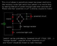
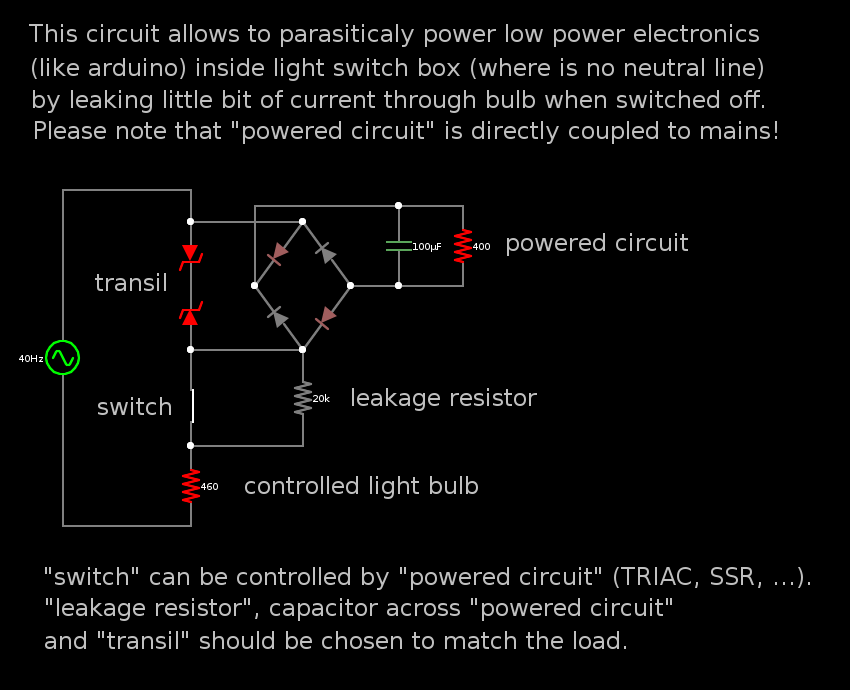
Hello, you may be familiar with the situation. You have old light wiring in your house, so there's one live wire and one wire going to lightbulb. And you want to roll your own smart switch connected to wifi or controlled by remote control. So you obviously miss the neutral wire and try hard to overcome this problem.

i've came with this:


Falstad circuit simulator code:

https://github.com/Harvie/Designs/blob/master/electronics/parasitic_switch.circuit

It's surely not the best way to power light switching electronics. What do you think about it? Will it work? Is there any room for improvement? What about fluorescent bulbs, LED bulbs, etc? How do you solve this problem?
 
Last edited by a moderator:

It should technically work, I cannot see any fundamental reason why it should not.

Only objection I can see is that there will still be power via the leakage resistor when the switch is off.
A cynic (or a lawyer) might argue that could pose a safety hazard to an unsuspecting person working on the light fitting.
 

I've replaced the "leakage resistor" by "leakage capacitor", which seems to be far more efficient.
 

a small TiNY switch (power integrations) buck ckt would be far more efficient and would not result in two series parts constantly in series with your load...
 

a small TiNY switch (power integrations) buck ckt would be far more efficient and would not result in two series parts constantly in series with your load...

But how should i connect it? I agree that switched design would be more efficient, but i don't know where to place it. it would still need some balast in series with bulb and parallel to switch. But in switched design both of these can be much smaller. But i am not sure how to wire it...
 

Status
Not open for further replies.

Part and Inventory Search

Welcome to EDABoard.com

Sponsor

Back
Top