Continue to Site

Welcome to EDAboard.com

Welcome to our site! EDAboard.com is an international Electronics Discussion Forum focused on EDA software, circuits, schematics, books, theory, papers, asic, pld, 8051, DSP, Network, RF, Analog Design, PCB, Service Manuals... and a whole lot more! To participate you need to register. Registration is free. Click here to register now.

3 Phase Induction Motor Driver Stage and Power Stage Design Help

Status
Not open for further replies.

Okada

Banned
Joined
Jun 16, 2016
Messages
1,159
Helped
129
Reputation
252
Reaction score
128
Trophy points
63
Activity points
0
I am designing 3 Phase Induction Motor V/F Control. I am planning to using dsPIC33FJ32MC202. There will be 6 SPWM signals. I want to know will there be 3 complementary sine wave PWMs ?

If yes, which signals are Complementary ?

The signals are

PWM1H1
PWM1L1
PWM1H2
PWM1L2
PWM1H3
PWM1L3

I am planning to use IRF540 for the driver stage.

My requirement is that I have to drive a 7.5KW Induction Motor. What should be the power rating of the power output stage ?

To increase the Power output should I use multiple IRF540 in parallel that is I have 6 SPWM channels and should I have say 8 to 10 IRF540 in each channel and in parallel to get the required power ?

Till now I have used PIC and generated 3 SPWM signals. If the other 3 signals are complementary that is 180 degree Phas shifted with the normal signal then I will use Not gates to get the other 3 signals and use PIC only. If this is not possible then I will use dsPIC33 but I don't know how to generate SPWM signals using dsPIC33. If needed I can post my PIC SPWM code.

Between PIC and Power stage there will be opto isolators.

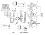
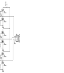
The IRF540 circuit is like this. Should I add 1 more IRF540 in parallel to each IRF540. IRF540 is rated for continuous drain to source current of 28 A.

My IM is rated at 7.5KW

IRF540 can handle VDS = 100 V DC.
 

Attachments

  • power stage.png
    power stage.png
    48.9 KB · Views: 140
Last edited:

Hi,

The naming is quite obvious:
* "PWM1" is the same for all signals.
* then follows "H" or "L": for High_side or Low_side
* then the number 1, 2, 3 for the phases.

"H" signals are complementary to the "L" signals. They are inverted, but include dead time to each other.

*********
My requirement is that I have to drive a 7.5KW Induction Motor. What should be the power rating of the power output stage ?
The power stage mainly is specified by "voltage" and "current". You don't give the voltage information....we neither can know this nor can we give a recommendation. The same is with current.

--> If you want to design sich a device, you should know what you are doing. Without the knowledge you risk your and other's lives. Additionally a wrong design (in the range of kW) easily may explode and verything may catch fire!

**********
Paralleling for increasing power:
....no recommendation without output_voltage, output_current, DC_voltage, switching frequency...

Klaus
 
  • Like
Reactions: Okada

    Okada

    Points: 2
    Helpful Answer Positive Rating
I am attaching the circuit. Download it and open it in mspaint and zoom it once.
 

Attachments

  • cir.png
    cir.png
    108 KB · Views: 260

For 200-300W motor probably it will work for a few seconds before blow up. For 7kW it will even not start.
 

Hi,

For 200-300W motor probably it will work for a few seconds before blow up. For 7kW it will even not start.
I even doubt it will withstand a few seconds.
If the IRF540 is specified with 100V VDS, but bus voltage is 300V.....expect a loud explosion and fire.

It really is very dangerous!!

Klaus
 
  • Like
Reactions: Okada

    Okada

    Points: 2
    Helpful Answer Positive Rating
That's why I asked whether I can use Multiple Mosfet's in parallel in each channel.
...................
If Multiple Mosfets can be used then what other modification is needed in the circuit so that it works for a 7.5 KW Induction Motor (IM) ?
 
Last edited by a moderator:

I think, you shoud gather more expirience with some low voltage RC brushless motors. Few years after you will be ready to work with real power electronics. For now it is too early for you.
We are just worring about your health.
 

Hi,

Learn the basics of electronics! ...to prvent anybody gets hurt.

That's why I asked whether I can use Multiple Mosfet's in parallel in each channel.

--> paralleling MOSFETs won't change Vds nor VBus. 300V will stay 300V and the limit of 100V is still true..

It's the same as temperature: 100°C will hurt you...and if there are a couple of friends with you...they all get hurt.

Klaus
 
  • Like
Reactions: Okada

    Okada

    Points: 2
    Helpful Answer Positive Rating
Even IRF740 and 840 will not fit savely. IGBT needed. Anyway, I will not support self distruction.
 

There's also a lack of specification. You are asking for 7.5 kW motor inverter but showing a three-phase bridge with 300 V bus voltage in your first post. This would refer to a 230V (actually only 210V) motor which is rarely made up to 7.5 kW power.

7.5 kW motors are usually made for 400 V supply, a respective inverter would need 560 V bus voltage, as generated by 400 V three-phase bridge rectifier. Thus you need semiconductors (MOSFET, IGBT) with >= 800 V rating.
 

@FvM

Please see the attached PDF. I have to modify it for a 7.5 KW 3 Phase Induction Motor. The VBUS voltage is obtained by 3-Phase rectifiers.

What should I change in the attached design ? TLP250 and IRF540 ?

You said that TLP250 cannot handle the voltages generated for a 7.5 KW system.

The bootstrap circuit has be changed also that is retaining UF4007 the bootstrap capacitor has to be changed. The PIC will be replaced by a single dsPIC33FJ32MC202 to get the 6 signals for the optically isolated IGBTs.

The Power Mosfets will be placed on the PCB. What should be the track width for the Drain and source connections ? I know high current will flow through these paths. Should I use 2 ox copper Glass Epoxy PCBs ?

I am not designing the generation of VBUS voltage for the Mosfets. I have been provided that voltage and I only have to design the drive circuit.

dsPIC33 part is complete.

Parallel Mosfets have to be used for the required currents ?
 

Sorry, Here is the PDF.

In this thread

https://www.microchip.com/forums/m928413.aspx

Post # 2

why he says that an isolated VBUS is required ?

Regarding the circuit in the PDF I should change the IGBT and Mosfets for a 7.25 KW system ofcourse changing the IGBT bootstrap capacitors ?

I will be using dsPIC33 Motor Control IC to get the SPWMs and PIC12F1840 to get 2 KHz PWM for the cooling fans.

Can I use the circuit in the PDF after changing the VBUS voltage, optically isolated IGBTs and Mosfets to higher power ones and IGBT bootstrap capacitors ?

Edit:

Sorry, TLP250 is not an optically isolated IGBT. I checked some wrong datasheet.

So, what components I have to change in the circuit mentioned in the PDF of previous post to design a simple 3-Phase Induction Motor Driver ? I only change the bootstrap capacitor, Mosfet Driver and Mosfet ?

What should be the VDS, VGS Id ratings of the Mosfets for a 7.5 KW system ? Are IGBTs better than Mosfets ? If yes, what voltage IGBTs I can use 1KV IGBTs ?
 

Attachments

  • V4I4_IJERTV4IS040346.pdf
    342.9 KB · Views: 133
Last edited:

You said that TLP250 cannot handle the voltages generated for a 7.5 KW system.
Don't know who said TLP250 can't be used for bus voltage of 600 V, I didn't.

I notice that the pdf (Indian project report) respectively post #3 schematic already uses silly 100 V IRF540 for 300 V DC bus. Suggests that the project report hasn't been edited thoroughly and probably shouldn't be trusted in other regards either.

It's clear that you need power semiconductors with sufficient voltage rating (I previously suggested 800 V as an absolute minimum) and sufficient gate driver capability according to the used power devices.

why he says that an isolated VBUS is required ?
Does it? I only hear about isolated high side gate driver supply, a possible (more ruggedized and reliable) alternative to bootstrap supply.
 

Ok.

@FvM

Please look at the A4 table in this link and tell me what is the current of 7.5 KW, 50Hz, 3-Phase Induction Motor.

https://www.electrical-installation.org/enwiki/Induction_motors

I am using 3 SPWM signals of 10 KHz and they are 120 degrees apart.

What I understood from the previous posts is to get 400V AC for the Induction Motor I have to provide 560V DC VBUS. So, from the A4 table for a 7.5 KW 400V AC 3 Phase Induction Motor Current is 15.5 A. Am I right ? If yes, can I use FGH30S130P IGBTs ? Datasheets attached. Can I use one of the two IGBTS mentioned ?

Which is better for the VBUS ? 560V from bridge rectifiers or from DC-DC supply as current requirement is less ?


Edit :

How about this ? STE40NK90ZD


You said Mosfet with min VDS max 800V. So, Is this a better Mosfet ? C2M0040120D. I think that these 4 devices can be used with proper heatsinks and cooling fans.

So, I retain the TLP250 circuit after changing the bootstrap capacitor and use it with C2M0040120D ?
 

Attachments

  • FGA50N100BNTDTU-Fairchild.pdf
    676.9 KB · Views: 111
  • FGH30S130P.pdf
    726.9 KB · Views: 90
  • STE40NK90ZD.pdf
    268.3 KB · Views: 103
  • c2m0040120d.pdf
    801.7 KB · Views: 109
Last edited:

I agree with the 15.5 A phase current calculation for 400 V motor supply. Industrial VFD for 7.5 kW motors have usually a higher maximum output current, e.g. 18 A.

Both IGBTs seem suitable.

Which is better for the VBUS ? 560V from bridge rectifiers or from DC-DC supply as current requirement is less ?
What kind of "DC-DC supply" do you imagine? Most industrial VFD run from three-phase (or single phase) rectifiers. Ideally they would use PFC power supplies with less harmonic input currents, but it's a considerable effort and power quality regulations didn't yet care about industrial VFD.
 

I agree with the 15.5 A phase current calculation for 400 V motor supply. Industrial VFD for 7.5 kW motors have usually a higher maximum output current, e.g. 18 A.

Yes, I have Implemented V/F system. frequency varies from 15 Hz to 50 Hz.

What kind of "DC-DC supply" do you imagine?

I have no Idea. I have to study a little regarding the power supply. Only thing I feel is using bridge rectifiers to get 560V DC is more dangerous than using DC-DC supply.

Please see the previous post. I updated it while you were reading it. Two more devices added. STE40NK90ZD and C2M0040120D.

- - - Updated - - -

I finally chose FGH30S150. Why it is mentioned in the datasheet as 30A in page 1 and then in absolute max ratings it is mentioned as 60A @ 25 degree C and 30A @ 100 degree C ? Now I have to design the DC-DC converter and Isolated Gate Drive for the IGBTs.

Is the 30A mentioned in big letters in page 1 heading is the max Id @ 100 degree C ?
 

Attachments

  • FGH30S150P.pdf
    743.5 KB · Views: 106

@FvM

In the other thread (Sine Wave Inverter) you said that Under-Voltage lockout has to be considered but the below

mentioned device has Under-Voltage Lockout protection.

AV02-0161EN_DS_HCPL-3120_2016-03-21

I have choosen 6x HCNW3120 for driving the Gates of the IGBTs.

These are optically isolated Drivers.

Now for calculating bootstrap capacitor value based on equation provided in this document ?

MQP_D_1_2.pdf page no. 28

tell me where I can find the required values for the equation.

Vf can be found in the bootstrap diode datasheet. Vf = 1.3V. I am not able to find the other things.

I was not able to find Gate charge in IGBT datasheet. IGBT datasheet in previous post.
 

Attachments

  • AV02-0161EN_DS_HCPL-3120_2016-03-21.pdf
    1.5 MB · Views: 101
  • MQP_D_1_2.pdf
    5.3 MB · Views: 113
  • 8ETU04S-Vishay.pdf
    493.3 KB · Views: 118

You really want to use a 8A rectifier as bootstrap diode? That's a bad idea. It has much too large junction capacitance. Use a smaller diode like US1M.

You find all necessary information about gate charge in the FGH30S150P data sheet. The "pure sine wave inverter" project report is quoting an IRF application note about gate driver calculation. You should study it thoroughly.
 

@FvM

Ok. I will use US1M. I downloaded the datasheet.

I don't want to use TLP250 or HCNW3120 as they are not high side and low side drivers. Shall I use IRS2186 instead with 4N37 ? As the two IGBTs are connected in half-bridge and as there are 3x half-bridges shall I use one 4N37 driving the input of one IRS2186 which drives the high and low side IGBTs of one half-bridge. So, a total of 3 4N37's and 3 IRS2186's. Is this better because Vs max of IRS2186 is 600 V and we are using a 560 V VBUS.?
 

Attachments

  • irs2186.pdf
    520.6 KB · Views: 93

Status
Not open for further replies.

Part and Inventory Search

Welcome to EDABoard.com

Sponsor

Back
Top