Continue to Site

Welcome to EDAboard.com

Welcome to our site! EDAboard.com is an international Electronics Discussion Forum focused on EDA software, circuits, schematics, books, theory, papers, asic, pld, 8051, DSP, Network, RF, Analog Design, PCB, Service Manuals... and a whole lot more! To participate you need to register. Registration is free. Click here to register now.

[moved] Query about VU meters (led bargraph)

Status
Not open for further replies.
Re: Query about crossovers

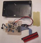
I bought one today and tried it just now I am probably using some wrong parts check this out.

https://www.youtube.com/watch?v=UbuRtk4uK9g

look at the Led's they arent working properly

I have made VU meters from the 3914 IC. It is normal for led's to flicker due to the irregular waveforms.

I see that the yellow led's are very bright. The green ones are dim. Try adding a resistor inline with each yellow led.

Here is something interesting to try... Hold a mirror so you see the led bar in it. Jiggle the mirror and you should see scope-like waveforms as the led bar sweeps across the mirror.
 

Re: Query about crossovers

The LM3914 is a linear voltmeter but the LM3915 is better for measuring the logarithmic relationship of loudness with our hearing.
My circuit uses a peak detector and its LEDs do not flicker, they show the exact levels of sounds. With no sound all my LEDs are off. With loud sounds all my LEDs are on at the same brightness. Half levels cause half the LEDs to be on. Your LEDs are operating completely wrong and are not showing loudness levels. Please post your schematic.
Maybe the messy wiring of your solderless breadboard is causing your LM3914 to oscillate.

The LM3914 and LM3915 do not need resistors in series with the LEDs because the LED outputs have regulated current. I have one resistor in series with the supply voltage to the LEDs to share the heating with my LM3915.
 

Re: Query about crossovers


this is what I used
 

Re: Query about crossovers

I describe your schematic.
Since pin 9 is disconnected then the IC is in the DOT mode where only one LED should light to indicate the input level but many of your LEDs are lit all the time. You do not have a peak or average detector (like I have) shown in the datasheet of the LM3915 so maybe it is normal for your LM3914 voltmeter LEDs to flicker and many to appear dim.

The datasheet of the LM3915 says that long wiring causes the IC to oscillate. They say and show a 2.2uF tantalum or 10uF electrolytic capacitor between the LED anodes common (pin 3 on your circuit) to ground (pin 2 on your circuit) with very short leads. The messy long wires on your solderless breadboard probably causes oscillation.

I tried my LM3915 sound level indicator project just now. In the DOT mode or BAR mode it works perfectly showing actual peak levels. It is not connected with wires, instead it has a microphone. I built the circuit compactly on stripboard.
 

Attachments

  • Sound Level Indicator 004.jpg
    Sound Level Indicator 004.jpg
    28.4 KB · Views: 98
  • audio wattmeter.png
    audio wattmeter.png
    197.8 KB · Views: 94

Re: Query about crossovers

Ok then I will try the build on a vero board then with the same circuit and hopefully it works good.
 

Re: Query about crossovers

The few jumper wires on my stripboard are 0.5" long or less.
If you use a peak detector circuit then a very short duration peak will look bright instead of dim.
Here is the high level simple peak detector shown on the datasheet of the LM3915:
 

Attachments

  • Simple peak detector.png
    Simple peak detector.png
    15.7 KB · Views: 144

Re: Query about crossovers

I did my first drawing with eagle, I am just learning I plan to Etch it and test it, So I added the schematic you gave me for the halfwave detector to the vu meter, I have some more to learn about eagle I only see old videos so basically I am just trying everything as I go, sorry for the lack of lables I just wanted to test it out.

Any tips about eagle.
 

Attachments

  • non invert.pdf
    135.3 KB · Views: 86
  • schematic.pdf
    106.9 KB · Views: 92
  • vu with halfwave peak detect.pdf
    115.6 KB · Views: 139
  • vu.pdf
    125.7 KB · Views: 96

Your schematic shows a PIC, not an LM3915 IC. Why does it have the un-needed attenuator R5 and R8? Pin 4 on the LM3915 must be connected to 0V.
Your schematic has no resistors and capacitor values and no supply voltage.
 

I used a pic because I cant find the lm3915 in eagle, I wont be sending it to a board house so does it matter if I use the correct chip, as long as it has has the same amount of pins and the correct package chip shouldnt it work?

Also I was in a hurry so I didn't label parts but I will soon, the lines that arent connected physically I gave them the same name so they are connected, Remember I am practicing at the same time, its my first circuit with the software, but I will do better next time.
 

It would take about 1 minute to copy the LM3915 circuit and the peak detector circuit from the datasheet and join them into a correct schematic without using Eagle that can do your pcb.
Did you remove R5 and R8?
What is your input signal level? The simple peak detector needs an input of about 10V peak to work properly so the signal must be amplified if a line level signal is used. 10V peak is 6.25W into 8 ohms.
 

R5 and R8 in my schematic is the same as R1 and R3 in the lm315 schematic that was posted in #5 post.

I didnt know you could copy things from a datasheet to eagle how would I do that?

I dont know what the input signal level is, I will be connecting the output of the amplifier to input of the circuit I posted (which is the peak detector circuit).

I think when I measured the output of the amplifier last time I was getting atleast 5v RMs so the peak should be up to 10v.
 

R5 and R8 in my schematic is the same as R1 and R3 in the lm3915 schematic that was posted in #5 post.
R5 and R8 are an attenuator to reduce the very high peak voltage from a high power amplifier from destroying what it feeds.
Electroschematics.com did not read the datasheet for the LM3915 that says its allowed input is plus and minus 35V which is 76.5W into 8 ohms and says if the amplifier power is more then simply add ONE resistor (not a voltage divider) in series with the input pin of the LM3915 that already has a resistor to ground.

But your input to the LM3915 is the output of the peak detector so you do not want to attenuate it, instead you might need to attenuate the input to the peak detector.

I didnt know you could copy things from a datasheet to eagle how would I do that?
You do not need to transfer a correct schematic to Eagle, instead you should post a corrected schematic here.

I dont know what the input signal level is, I will be connecting the output of the amplifier to input of the circuit I posted (which is the peak detector circuit).
Of course you can calculate the signal level from the amplifier if you know its rated continuous average output power or its supply voltages.

when I measured the output of the amplifier last time I was getting atleast 5v RMS o the peak should be up to 10V
5V RMS into 8 ohms is a small power of only 3.125W. The peak voltage of 5V is 7.07V which is not enough for the peak detector circuit. The top 10th LED will never light because it lights with an input of 10V.
 

I was using a 4 ohm to test the circuit, the specs on the amplifier circuit (**broken link removed**) didnt let me know if the peak power is 700w or the rms is 700w but my supply voltage I am using is 40-0-40 ac. when I tested the amp I used a 8ohm speak and a 8 ohm coil in parallel so thats 4 ohms and my laptop volume was at 40 percent high the most.

so probably my amplifier needs a pre-amplifier what d you think?
 

With a dual 50VAC transformer the amplifier produces 700W into 4 ohms continuously with low distortion but it is clipping a little. In your other thread about that amplifier I looked at it beginning to clip at a few hundred Watts on its datasheet. With a dual 40VAC transformer it will be about 200W to 400W.

When you tested the amp you do not know how much power it produced.
A volume control is logarithmic to match our hearing so if the amplifier begins to clip with the volume control set to maximum (but it usually has more gain so that a lower input signal level can produce maximum output) then when the volume control is set to 50% the output voltage is 10% to 20% resulting in the power being 20W to 80W. Your volume control setting and the resulting output level was less.

I do not know if the signal level from the laptop needs a preamp for the amplifier to supply full output power to break all the windows in your neighbourhood! I retired my old 70W per channel amplifier that shook my home with 4 channels and now I am using my very old 18W per channel amplifier that sounds and feels about the same. Are you the guy making a high power audio system for a bicycle?
 

Well yes I need it to be at its best because as I said its for an out door setting in a big private space so if a preamp could push it more then that would be good. so at its current state I cannot use the peak detector circuit with the lm315 then because the output is too low?

something you explain I don't really understand fully. so far I haven't even added the volume control pot. for me to pull more power to test it fully I would need to load the output with a more powerful load in this case more speakers?

could you recommend a schematic for a good preamp for this amplifier I only need a volume control on it with good enough gain.

No not the guy for the bicycle audio system.

- - - Updated - - -

updated schematic.
 

Attachments

  • schematic.pdf
    108.7 KB · Views: 106

ebay says the sensitivity of the cheap Chinese amplifier is 1.6V so it will not produce anything near its rated output without more gain from an external preamp. I think a preamp with a voltage gain of 10 times will be good, then for most signal sources the volume control can be turned down a little and there will be extra gain for lower level signal sources.
 

Ok I did some reading so I need something with about 20db

what about this?


Next.GR seem to nothing about electronics. They show an old MPF102 as a Mosfet but it is not, it is a Jfet. It has such a wide range of gain that some would have too much gain and be saturated and others would have such low gain that they would be cutoff. You do not need its very high input resistance. It is so old that it is not made anymore. Use an opamp and two resistors to set its gain.
 

on the page it actually said it was a Jfet but not much more, so are you saying I should still use this circuit but add a opamp and 2 resistors to set gain and remove the 2.2m at the input?

- - - Updated - - -

did you mean something like this?
 

Attachments

  • gain.pdf
    96.6 KB · Views: 77

Status
Not open for further replies.

Similar threads

Part and Inventory Search

Welcome to EDABoard.com

Sponsor

Back
Top