Continue to Site

Welcome to EDAboard.com

Welcome to our site! EDAboard.com is an international Electronics Discussion Forum focused on EDA software, circuits, schematics, books, theory, papers, asic, pld, 8051, DSP, Network, RF, Analog Design, PCB, Service Manuals... and a whole lot more! To participate you need to register. Registration is free. Click here to register now.

Buck converter doesn't work with a battery as load

Status
Not open for further replies.

Billben

Newbie level 2
Joined
Jun 2, 2016
Messages
2
Helped
0
Reputation
0
Reaction score
0
Trophy points
1
Activity points
28
I have the same problem with the one asked in this thread
https://www.edaboard.com/threads/244946/
but I don't find it helpful, I didn't find a solution for that.

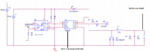
I'm designing a battery charger using IR2111 driver, it works well with a resistive load an not at all with a 12V battery.

Here is the circuit diagram

Can you help me please :-(
 

Attachments

  • buck.png
    buck.png
    25.6 KB · Views: 170

Check out the "typical connection" on page one:
https://www.infineon.com/dgdl/ir2111.pdf?fileId=5546d462533600a4015355c810e51682
The problem is that the upper mosfet is not getting any gate drive power.
If you are using the bootstrap system to get gate drive power, the lower mosfet absolutely must be there, or the circuit can never start up.

The gate drive circuit of a simple buck regulator really needs a full time fully isolated power source, or you are going to have problems at start up and extremes of duty cycle.

As a temporary fix, try connecting a 9v battery across C3. That should get it working, but its obviously not a proper cure.
 

Yes better to use a P fet that doesn't need a bias supply and a different controller to drive it...! then it will work...
 

Yes better to use a P fet that doesn't need a bias supply and a different controller to drive it...! then it will work...
That is an excellent idea.

But there is one small point you might need to be a bit careful about.

As Easy says, it requires an "opposite sex" type of controller where the output function, under voltage lock out, PWM, and feedback functions are all inverted.

Either that, or just invert the gate drive.
Even then you need to be a bit careful that the gate driver has an under voltage lock out that works the right way around. Most do not.
 

You seem to want to use the IR21XX controller, so in order to get some charge in that bootstrap cao at startup, you can put a high value resistor across the buck diode……..that will start it off for you….as long as you wait for the boot cap to get charged before you aply pwm.
But really you want to be using a dedicated buck controller such as the linear.com ones like LT3892 ETC ETC…or any other semico.
Or do a sepic instead.

I don’t see any feedback. If you are regulating the current and not the output voltage into the battery, then it shouldn’t be a problem to regulate it…but if you are trying to regulate the voltage across the battery at full charge, then that can be a problem, as the batt is like a enormous value cap, and so your compensation will need to take that into account……but its not a problem if you are closing the loop round the batt charge current.
 

With 12V acc as load, must double voltage V1 and V3 for proper working.
 

You must not increase V1 as it would damage the driver IC and MOSFET. As already mentioned by others, to use a bootstrap driver in this application, it must be supplemented by start-up circuit.

A straightforward solution would be to extend the circuit to a synchronous buck by adding a low-side MOSFET, and limit the duty cycle slightly below 100 percent.
 

Sure, IC voltage must be limited below maxim value.
Battery modify buck working equation, for Vout<Vbat no current flow...so no energy in inductance.
 

Warpspeed:
"try connecting a 9v battery across C3". As you sad it works, but not a proper cure. :-(

iop95:
The maximum power supply supported by IR2111 is 25V. I can feed it with 24V with zener diode. it is not a good idea but I think it is the only sollution I have.

FvM:
I don't need a low side MOSFET, so why adding it will fix the problem :/ ?


Guys after a long time, I'm still facing this problem.
The solutions that I had which are not good are:
1- Making the power supply of the driver 24V which is a bad solution as the maximum power supply is 25V.
2- Using TLP250 instead of IR2111. But the disadvantage of this is I should have an external power supply (I mean the two power supplies can not share the same ground)

If you have better solutions please share them, thank you.
 

You just need to replace the 9v battery with a proper isolated dc power supply.

Easiest way to do that is use a 12v to 12v isolated one watt power module, these are available on e-bay for just a few dollars.
This is just one example, there are plenty of others.
**broken link removed**

Then power both the above power module and the rest of your control circuit from the solar panel via a 7912 voltage regulator. The regulator will be needed because the solar panel can go well above 16 volts.
 

Hi,
Since it's about battery charger, try and understand the algorithm of charging a battery. From your circuit, I will suggest 16-18v input, and a voltage feedback sensor to the controller. Current can be added for better monitoring. Note due to battery's load impedance, this feedback might be a way out. Good luck.
 

Status
Not open for further replies.

Similar threads

Part and Inventory Search

Welcome to EDABoard.com

Sponsor

Back
Top