kathmandu
Full Member level 5
Hello,
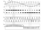
I want to implement this unipolar PWM algorithm for a sine wave inverter (to drive a h-bridge):

However, as you can see from the diagram above, the PWM pulses for the two h-bridge legs (Vg1 and Vg3) have a variable alignment.
That's it, at the begining of the cycle they have a left alignment, they slowly turn to center-alignment (around the peak voltage of the sine wave) and they become right-aligned toward the zero crossing point.
I'm going to use a look-up table to generate the pulse duration but how to dynamically change the pulse alignment during normal operation?
I'm using a Freescale MCU having hardware PWM timers. I know how to set those timers to get left/right-aligned or center-aligned signals but how to choose an alignment in-between??
I thought of using fixed alignment schemes though, BUT..
.. If I'm going to use a center-aligned scheme, I'll get pairs of two identical pulses with the same duty-cycle for every iteration.
.. If I'm going to use left-aligned pulses, I'll get a single pulse for each iteration but the resulting signal will have a variable frequency (and duty-cycle, of course).
Any help is greatly appreciated.
PS: I could try to draw a diagram if my last explanations were confusing.
I want to implement this unipolar PWM algorithm for a sine wave inverter (to drive a h-bridge):

However, as you can see from the diagram above, the PWM pulses for the two h-bridge legs (Vg1 and Vg3) have a variable alignment.
That's it, at the begining of the cycle they have a left alignment, they slowly turn to center-alignment (around the peak voltage of the sine wave) and they become right-aligned toward the zero crossing point.
I'm going to use a look-up table to generate the pulse duration but how to dynamically change the pulse alignment during normal operation?
I'm using a Freescale MCU having hardware PWM timers. I know how to set those timers to get left/right-aligned or center-aligned signals but how to choose an alignment in-between??
I thought of using fixed alignment schemes though, BUT..
.. If I'm going to use a center-aligned scheme, I'll get pairs of two identical pulses with the same duty-cycle for every iteration.
.. If I'm going to use left-aligned pulses, I'll get a single pulse for each iteration but the resulting signal will have a variable frequency (and duty-cycle, of course).
Any help is greatly appreciated.
PS: I could try to draw a diagram if my last explanations were confusing.
