Continue to Site

Welcome to EDAboard.com

Welcome to our site! EDAboard.com is an international Electronics Discussion Forum focused on EDA software, circuits, schematics, books, theory, papers, asic, pld, 8051, DSP, Network, RF, Analog Design, PCB, Service Manuals... and a whole lot more! To participate you need to register. Registration is free. Click here to register now.

Query about crossovers

Status
Not open for further replies.

Enzy

Advanced Member level 1
Joined
Mar 20, 2016
Messages
488
Helped
2
Reputation
4
Reaction score
2
Trophy points
18
Activity points
4,607
I bought 2 assembled boards on ebay built around IRs2092, not sure if I can share that link here, its for 2 mono amplifiers it says 700 watts @ 4ohms not sure if thats peak or RMS, not sure if it will produce that though I think its a class D amplifier I havent received, I hope the heat sink is good enough for that power if it can deliver it.

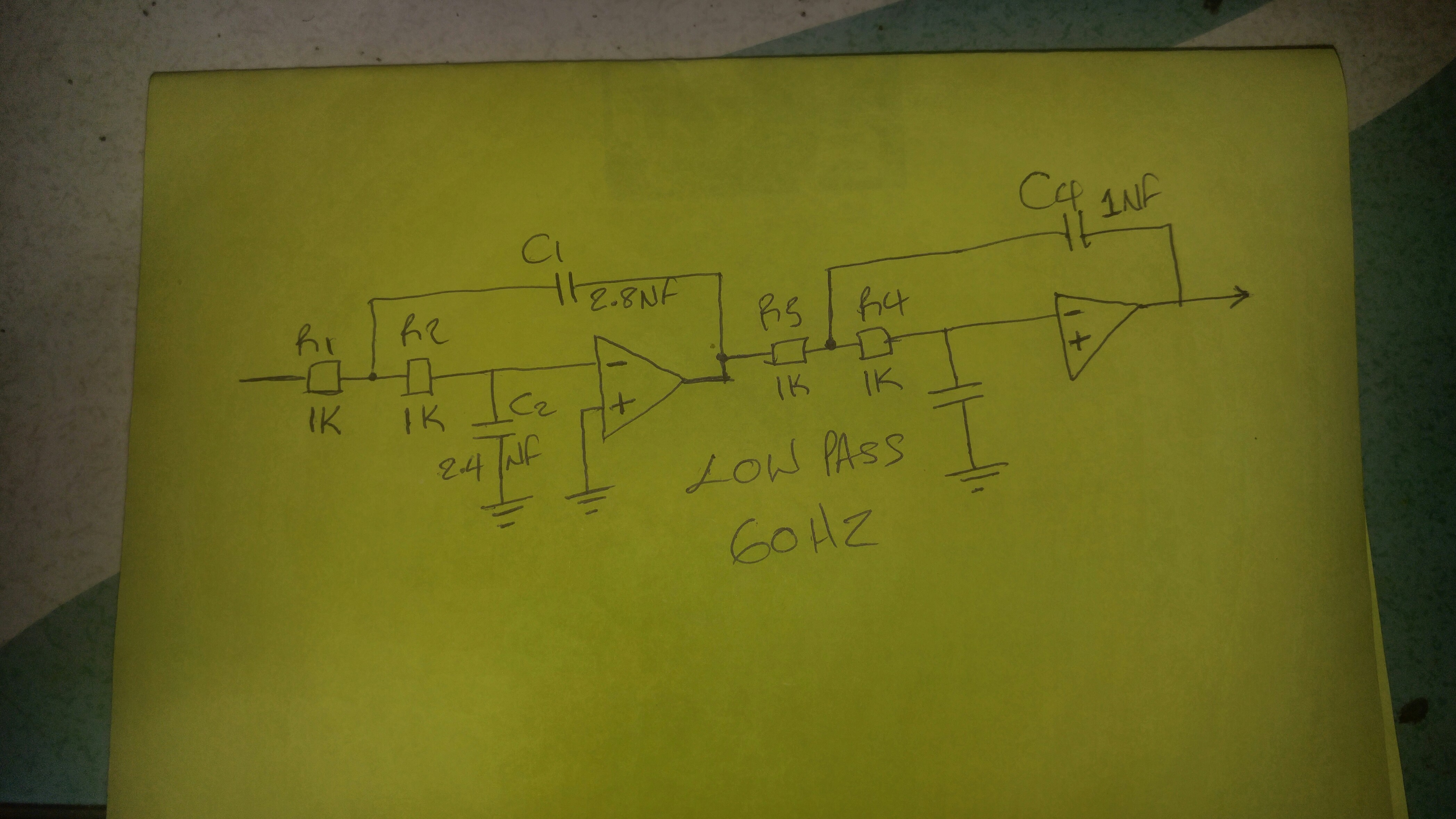
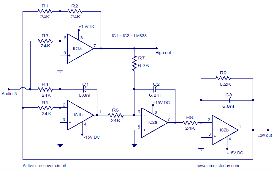
I am going to use it to play bass and I am now doing some reading on cross overs normally in cross overs I see big coils and big resistors and capacitors, I would see them in stores in my country but they are never labeled so I have no clue what they are for and should be used on but I would think those types are passive cross overs, based on my readings active cross over would be the better choice.

I do not know if there is a limitation to cross overs like that meaning, I saw a circuit online which I would like to use but because It is so simple I am wondering if by some chance it will limit the power.


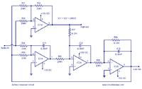
for example using my laptop as the signal source I would go from my laptop to this cross over then out to the amplifier? Also I would only use the low side since I only need bass so only the bass signals would be amplified that seems like the best way based on the readings.

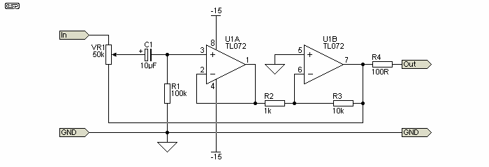
This is a project also how would I add volume control to this, I would need to know the input resistance to put a pot before the cross over but not sure how to determine that.

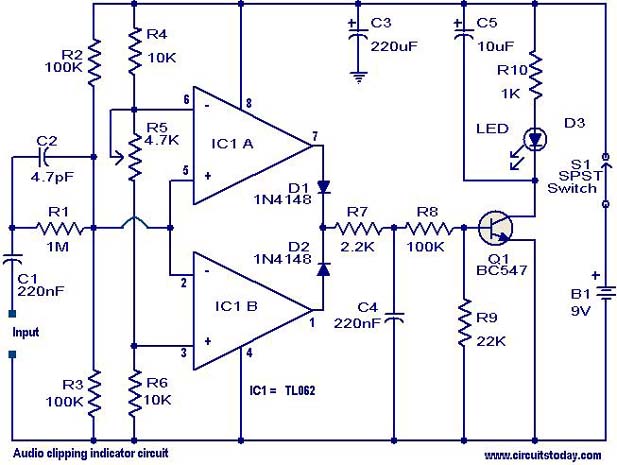
I plan to add a clip light detector circuit and a VU meter to this, is there any other feature thats good to include in n amplifier like protection.


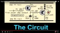
Clip light detector.
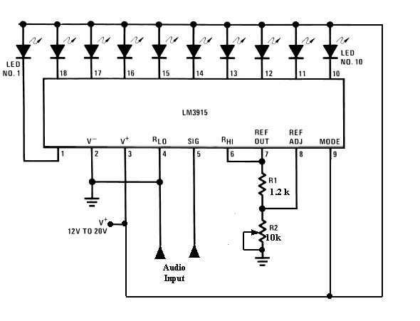


Vu meter.
 

The crossover circuit and the clipping detector circuit are poor quality "Mickey Mouse" circuits.
A real active crossover circuit has a highpass section and a separate matching lowpass section. This circuit has a lowpass section then the highpass is "derived" and does not match which is bad.
You want to use only the lowpass part then why not make a proper Butterworth lowpass filter? But you need the tweeters to have a matching highpass filter so that the crossover frequencies are not played by both the woofer and the tweeter causing a boost in the sound (or a notch) at the crossover frequency.

The clipping detector will damage the base-emitter junction of the BC547 because its voltage will exceed the maximum allowed reverse bias of voltage of 6V most of the time. Then the junction will have avalanche breakdown that melts away the junction that is not designed to get hot.
 

Ok I am doing some reading on that type of cross over now then thanks ill show you what I come up with in a bit, also what I am thinking is where exactly would I cut off my bass frequency I was thinking 100hz, I am not sure if I would hear voices through speaker at that frequency.

- - - Updated - - -

or probably down to 60hz, also could you explain the part about the volume control to me, or is it just safe to try a 50k or 100k pot before the cross over.

- - - Updated - - -


I did that just now, I doubt I would be able to get all the parts exactly as I want them but is this a god circuit.
 

If you are going to use active crossover system

1. your circuit must be able to handle considerable power (if you are using the power output)
2. OR you must provide different amplifiers for low and high (if you are using crossover before the power amplifier)

If you are going to use passive crossover system:

1. You need to get your hands dirty and make the coils by hand because they will sit inside the speaker boxes...

The great thing will be that even an ordinary set of speaker may sound real great...
 

If you are going to use active crossover system


2. OR you must provide different amplifiers for low and high (if you are using crossover before the power amplifier)

I will only need the low pass for the bass and the plan is to to put it before the amplifier, in that case a circuit such as what I just showed, would it be able work with any power amplifier no matter the wattage.
 

Ok so I guess that the cross over circuit is ok then.


I found this clip light circuit.
 

You made a lowpass filter with the opamps wired completely wrong. I show a corrected circuit.

Why do you want to cutoff low frequencies? Usually low frequencies are cutoff only to reduce interference from mains hum or trucks traffic. Maybe you are confused and instead you want to cutoff high frequencies?
Why? Music and voices need high frequencies.

The clipping detector might work fine if you use a low noise audio dual opamp.

- - - Updated - - -

You cannot connect a volume control to the input of an active filter because its resistance will mess up the frequency calculation. The active filter must be fed from a very low impedance like the output of an opamp.
 

Attachments

  • lowpass filter part of a crossover.png
    lowpass filter part of a crossover.png
    458.1 KB · Views: 98

the circuit I did I was trying to make the cut off frequency at 60hz remember its for bass, so the purpose is to block anything higher than 60hz.

The input to the cross over would come from the laptop then from the cross over to the amplifier.
How would I integrate a volume control if I use a active filter.
 

How would I integrate a volume control if I use a active filter.

You can use a level control at the output of the active filter /input of the power amplifier. You should use a log scale potentiometer for more gradual effect.
 

You can use a level control at the output of the active filter /input of the power amplifier. You should use a log scale potentiometer for more gradual effect.


What about using this as a volume control, placing it after the cross over?
I could not find much info about the level control.
 

This is also having some gain and you need to ensure that the input of the power amp is not overloaded. This is also inverting the input and that may or may not be desirable in some cases...
 

Could I get an example of a circuit I could use?


Also the parts I used in the cross over I did audioguru said I did it wrong but he isnt back as yet to here what I said could you look back and check what I did and see if thats ok.
 

Could I get an example of a circuit I could use?.

Please see his post #7; this is a standard filter. You can use a volume control after the circuit using a simple 50K log pot taking the out off the wiper.

Also read a bit more on butterworth and chebyshev filters from the internet. Butterworth filters are very popular because they can be handled very well mathematically.

In this case, the volume control is nothing more than 50K log pot - you may need to connect a 100E with the wiper to offset the output impedance.
 

I saw it, I did the hand drawn version but I need it to cut off at about 60hz because I need it to only send bass frequency to the amplifier, so the values he used in his version would those be the correct values t play bass frequency or is my hand drawn version the one with the correct values, I used a butterwoth filter calculator to calculate the values that's why I am asking.
 

You can change the values in a filter for any cutoff frequency you want. I copied another lowpass filter circuit to show you that your opamps were wired completely wrong.
Your filter calculator is stupid because it selected capacitor values that do not exist. It should have selected standard capacitor values then resistor values that go with them.

Now you posted a circuit with a volume control and TWO opamps. Why does it use TWO opamps and why does it use any opamps? The lowpass filter can feed the volume control and the volume control can feed the power amplifier without the two opamps.
 

ok then I will work with your low pass filter, also with the volume control I can use just a 50k pot?
 

You must look at the input impedance of the amplifier to select a suitable resistance value for its volume control. The resistance of the volume control should be half the amplifier's input impedance or less.
 

You must look at the input impedance of the amplifier to select a suitable resistance value for its volume control. The resistance of the volume control should be half the amplifier's input impedance or less.

That was a question I asked early but didnt get a reply to I was asking how do I know what the input impedance of the circuit to know what value put to use.
 

**broken link removed**

this is the amp.

so I would assume the impedance is: Driving point impedance:14KΩ
 

Status
Not open for further replies.

Similar threads

Part and Inventory Search

Welcome to EDABoard.com

Sponsor

Back
Top