Continue to Site

Welcome to EDAboard.com

Welcome to our site! EDAboard.com is an international Electronics Discussion Forum focused on EDA software, circuits, schematics, books, theory, papers, asic, pld, 8051, DSP, Network, RF, Analog Design, PCB, Service Manuals... and a whole lot more! To participate you need to register. Registration is free. Click here to register now.

[SOLVED] Best way to switch 12V usin a PIC.

Status
Not open for further replies.

JohnJohn20

Advanced Member level 4
Joined
Feb 2, 2012
Messages
111
Helped
0
Reputation
0
Reaction score
0
Trophy points
1,296
Activity points
2,377
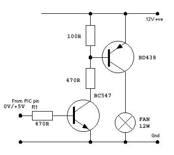
Hi. I am using a pic to switch the +12V line to a 12 watt fan (I want to switch the +12V line rather than the 0V because I want the 0V line to always be connected to the fan so I can monitor the tacho).


Originally I had a 4k7R across the emitter and base of the BD438, but it didn't turn off properly. Even with the 220R, there is still about 0.4V across the fan.

Could this circuit be modified to get a 100% on/off?

Could I use a MOSFET to do this? What would be an example of one that could replace the BD438?

Thanks.
 

There is no reason in principle why that wouldn't work. When the BC547 is turned off, the bias current for the BD438 is completely removed. It is just possible you are creating some kind of latch-up action or overheating as there is nothing to limit the base current in the BD438. I would suggest you moving the top 220R so it is only in series with the BD438 base and replace it's original position with 4.7K. That will limit the base current and still ensure it turns off properly.

I think I would increase the resistor in the base of the BC547 to 1K as well. When you use 220 Ohms, if the PIC produces (or tries to produce!) 5V, it will try to pass (5-0.6)/220 = 20mA which is higher than needed and getting close to the limit for a standard PIC I/O pin.

Brian.
 
Tried this (see image) but I am still getting 0.4 volts across the fan. I suspect it is not possible to get zero volts using BJTs How can this be done with MOSFETs?
 

I think you have a defective transistor. I think you destroyed the BC547 by using it to drive the short circuit you had.
12W from 12V is a load resistance of 12 ohms. You measure 0.4V across it so its leakage current is 0.4V/12 ohms= 33.3mA which is a lot.

It is easy to find out of the BD438 is good and the BC547 is bad, simply short the base-emitter of the BD438 (the 100 ohms) and see if the leakage goes away.
 
Hi,

Try to connect a 1k resistor in parallel to the load.

My idea behind this: maybe there is a semiconductor device (bjt, fet, diode..) inside the load, that makes it high impedance at low voltages. Then any small leakage current may cause what you observe.

Btw. Use a BE resistor of about 1k at the upper bjt. 100s of kOhms are useless.


Klaus
 
Thanks Audioguru, you may be right as the BC547 has since died completely.

Thanks Klaus. Makes sense. I will experiment.

I take it from your suggestions that there should be no leakage happening. Just thought it might be normal to have a very small leakage through the BC547 being amplified by the BD438. So I conclude that something else is not right.
 

The datasheet for a BC547 shows that its collector to base leakage current is only 100uA when it has no base-emitter resistor and has a voltage across it of 50V or more. Yours has a leakage current that is 33mA/100uA= 330 times higher when it should be much lower since your voltage is much lower.
 

Status
Not open for further replies.

Part and Inventory Search

Welcome to EDABoard.com

Sponsor

Back
Top