Continue to Site

Welcome to EDAboard.com

Welcome to our site! EDAboard.com is an international Electronics Discussion Forum focused on EDA software, circuits, schematics, books, theory, papers, asic, pld, 8051, DSP, Network, RF, Analog Design, PCB, Service Manuals... and a whole lot more! To participate you need to register. Registration is free. Click here to register now.

Wide range LC oscillator, single ended PSU?

Status
Not open for further replies.

neazoi

Advanced Member level 6
Joined
Jan 5, 2008
Messages
4,119
Helped
13
Reputation
26
Reaction score
15
Trophy points
1,318
Location
Greece
Activity points
36,918
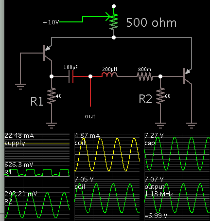
Hi, can this oscillator be used with a single ended PSU by making some mods to it?
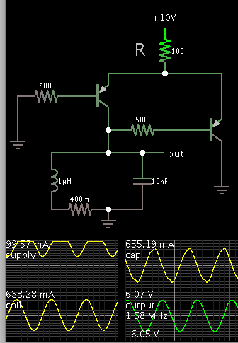
Or else, is there an easy way to get a symetrical PSU of +/-5V out of a single ended 10V one?
Note that this is an RF circuit so I do not know how well a floating GND would work.
 

Attachments

  • LCosc.pdf
    228.9 KB · Views: 105

It would be difficult to modify that design to work on a single supply because of the 'AGC' circuit around T3 and the way it provides bias for T1 and T2.
However, the negative supply does not have to accuarately mirror the positive one as long as it remains stable. Your easiest solution would be to feed 5V directly from a PSU to the positive line and use an inverter circuit to generate the -5V from +5V. You could use a ready made module (NME0505 for example) or build your own using an ICL7660.

Brian.
 
  • Like
Reactions: neazoi

    neazoi

    Points: 2
    Helpful Answer Positive Rating
Don't think that it's too difficult to use a "virtual" ground a mid supply because the present ground node has only weak DC load.
 

This LC oscillator produces positive and negative waveforms, which can be tapped at a few places.


Original schematic at (page 97, figure 7b):
 
  • Like
Reactions: neazoi

    neazoi

    Points: 2
    Helpful Answer Positive Rating
I would be tempted to use a 78L05 five volt regulator, and a REAL ground.

Then generate minus five volts from an ICL7662 voltage pump off the +5v supply.

A regulated +5v will give better frequency stability, the -5v only really controls the amplitude via a current source, which is much less critical.
I would still much prefer to see all the RF components tied down to a REAL ground.

- - - Updated - - -

Another completely different way to go about this, and with only one supply would be a Lambda oscillator, plenty of info on the internet about Lambda oscillators.

http://users.tpg.com.au/users/ldbutler/NegResDipMeter.htm

With only two components you will have an oscillator that amazingly will work from low audio frequencies well up into the VHF range.

Connect it to just about any parallel tuned circuit and it will oscillate, and you can then use a digital frequency counter (with very loose coupling) to tweak up all your LC circuits in situ.
 
Last edited:
  • Like
Reactions: neazoi

    neazoi

    Points: 2
    Helpful Answer Positive Rating
This LC oscillator produces positive and negative waveforms, which can be tapped at a few places.


Original schematic at (page 97, figure 7b):

Hey, that's an LC multivibrator isn't it? Interesting, although I have no idea about the frequency drift of it. Also an ungrounded LC does not seem to me a goot idea.

- - - Updated - - -

Another completely different way to go about this, and with only one supply would be a Lambda oscillator, plenty of info on the internet about Lambda oscillators.

http://users.tpg.com.au/users/ldbutler/NegResDipMeter.htm

With only two components you will have an oscillator that amazingly will work from low audio frequencies well up into the VHF range.

Connect it to just about any parallel tuned circuit and it will oscillate, and you can then use a digital frequency counter (with very loose coupling) to tweak up all your LC circuits in situ.

I did not had too much success with an Lambda oscilaltor I have tried before. It oscillated fine in wide range, but the waveform had severe distortions. It surely needed an LPF after it.
My best success till now is this oscillator https://www.edaboard.com/threads/351615/ which oscillates from 1-21MHz with a very low distortion.

Also there is another oscillator I need to try https://www.edaboard.com/threads/354866/ but I am waiting for your comments on it.
 
Last edited by a moderator:

I use J176 P-JFETs in a similar Lambda application and it works well into the VHF region. You can use one FET and a bipolar transistor if suitable bias resistor are added but the RC element of the resistors in series with the base capacitance limits the top frequency.

I have a "I'll get round to finishing it one day" HF receiver project that uses PWM to generate the Lambda voltage and periodically, (every few mS) raises the voltage to oscillation point measures one or two cycles to check the frequency then backs the voltage off slightly. The tuning is varactor controlled. The idea is it gives keyboard control of the frequency using software FLL and maintains the circuit at maximum 'Q' by finding the point just before the tuned circuit breaks into oscillation. A kind of 'self-adjusting' regenerative receiver. If I can filter out the periodic oscillation pulses, the audio should be reasonably good quality and by reversing the algorithm so it is 'just' over the oscillation point instead of under it, it makes a CW/SSB receiver.

Brian.
 
  • Like
Reactions: neazoi

    neazoi

    Points: 2
    Helpful Answer Positive Rating
Brian, I too have a glacially slow full HF band receiver/transmitter project under construction.

The Lambda oscillator I use has a 2N3820 P channel Jfet, which is the difficult half of the pair to obtain. Almost any common N channel Jfet will work fine with that.

It will oscillate merrily at almost any frequency, but like most oscillators the amplitude will grow until something clips or distorts. So some distortion is inevitable, especially if the tuned circuit Q is fairly low.

If you absolutely must have low distortion and a fixed output amplitude, an automatic gain system in the feedback is essential. But if all you want is an oscillation frequency to measure, then the distortion can be ignored.
 

Hey, that's an LC multivibrator isn't it? Interesting, although I have no idea about the frequency drift of it.

It is built on the long-tail pair principle. It operates a little differently from cross-coupled transistors (as seen in the classic astable multivibrator).

Also an ungrounded LC does not seem to me a goot idea.

This oscillator has an LC tank circuit connected to ground. It also has the long-tail pair.

7383322500_1464104304.png


- - - Updated - - -

Notice the output is +/- AC.

Current flow in the tank circuit can reach several times the amount drawn from the supply.
 

Status
Not open for further replies.

Part and Inventory Search

Welcome to EDABoard.com

Sponsor

Back
Top