Enzy
Advanced Member level 1
I plan to build this inverter but I am seeing some comments about it having a high standby current draw like 6 to 8 amps, just by looking at the circuit do you think this is true and if so how could that be fixed.
Follow along with the video below to see how to install our site as a web app on your home screen.
Note: This feature may not be available in some browsers.
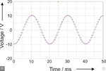
Six amps at 12v is only 72 watts, which is quite low for a 5Kw inverter with a low frequency output transformer.
To do better, you will need a much more efficient output transformer that has a much lower no load magnetising current.
Try connecting the secondary of the transformer you plan to use direct to the 220v mains supply and measure the current it draws under no load.
Usually no load power is not an important design consideration for most transformers.
The designer tries to design it to produce the rated output power using as little iron and copper as he can get away with. He is not designing this for fun, but to make something he can sell for a profit. To stay in business he needs to make it as cheaply as possible.
So you get something that always runs warm, even with no load, and always sucks a fair bit of power, even with the output disconnected.
Only way to do any better is to design and wind your own scratch built transformer, where cost and size is of no concern. It will be better, but probably still way short of what you would really like to have.
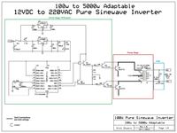
I consider it rather generous to describe it as "pure sine wave". The output will be AC but the waveform certainly won't be a pure sine and it will change according to the load current.
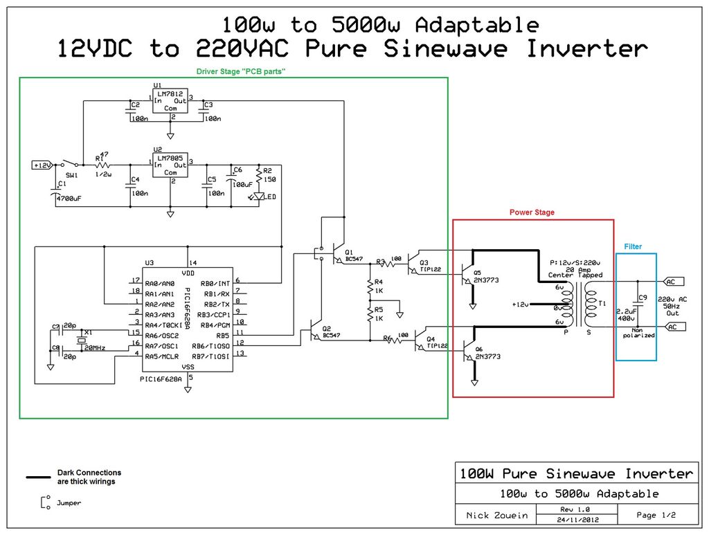
I also have serious reservations about the drive available to the output transistors. There are four PN junctions (two in the TIP122) to overcome before the PIC output voltage can possibly saturate the output transistors. From the data sheets, it needs something around 4.7V drive and I suspect under load the PIC can't produce that reliably. It would make far more sense to use Q1 and Q2 as common emitter inverter stages so their collectors can make use of the 12V supply.
Brian.
The current will be high when the output is shorted or heavily loaded. Without a load then the current is low.
You have an LM7812 being fed with 12V so it will not regulate. Its minimum input is 14.5V.
Never said it was efficient, only that is pretty normal for this type of inverter.SO your telling me if I have an inverter powered by 12v and has no load running that 6 amp standby current is nothing how can that be efficient,
Yes it is a lot of wasted energy, and it will drain batteries fast.I thought that would be considered a lot of wasted energy that should drain batteries fast.
Haha, you will never see that from a low frequency transformer type of inverter.Shouldn't it be pulling milliamps when its not under load?
I don't think so, the only way that kind of PIC can do that is to generate the sine voltage using PWM and even then doing it in software as that type doesn't have PWM hardware. Even if it was using PWM, the circuit would be incredibly inefficient to use an iron core transformer to filter HF PWM.I was thinking that the Pic is generating a stepped sinewave and the transistors are a crude linear amplifier. Then the transistors will heat as much as the load.
No, I'm saying to use the BC547 transistors as inverters. ALL the voltage reaching the output transistors comes from the PIC at the moment but it loses ~1V as it passes through each transistor, that doesn't leave enough to ensure the output stage is full switched. In fact you could remove the 12V regulator completely and connect the BC547 collectors to 5V and it would still work exactly the same. If you make a minor change it is all fixed - just connect the emitters of the BC547s to ground, put the 1K resistors and 100 Ohm resistors to the collector and feed them from 12V, also add 470 Ohm resistors between the BC547 bases and the PIC. If you do that, only two extra resistors are needed and it ensures the output stage can be hard driven.So in other words do you mean you think it would be better to remove the tip 122 transistors from the circuit and use the bc547 to feed the 2n3773 transistors? By the way Is there anything in the T0-3 package that I could use instead of the 2n3773 transistors even if its a lower power rating.
The circuit does not need a 24V regulator and it will not work anyway since its minimum recommended input is 27V.I would want to use 24v to run my inverter I already have a 24v transformer for the project I was thinking of using a 24v regulator in place of the 12v regulator
The circuit does not need a 24V regulator and it will not work anyway since its minimum recommended input is 27V.
Your 24V transformer voltage is too high since the transistors have some voltage loss. You might need a 20V transformer.
I hear most replies suggesting to use a different circuit.do you think I should work on modifying this design to something thats good enough or should I use a different circuit all together