Continue to Site

Welcome to EDAboard.com

Welcome to our site! EDAboard.com is an international Electronics Discussion Forum focused on EDA software, circuits, schematics, books, theory, papers, asic, pld, 8051, DSP, Network, RF, Analog Design, PCB, Service Manuals... and a whole lot more! To participate you need to register. Registration is free. Click here to register now.

[SOLVED] Stepper Motor not working properly

Status
Not open for further replies.

LeoStar

Member level 2
Joined
Nov 19, 2014
Messages
50
Helped
0
Reputation
0
Reaction score
0
Trophy points
6
Activity points
500
Hello Everyone!

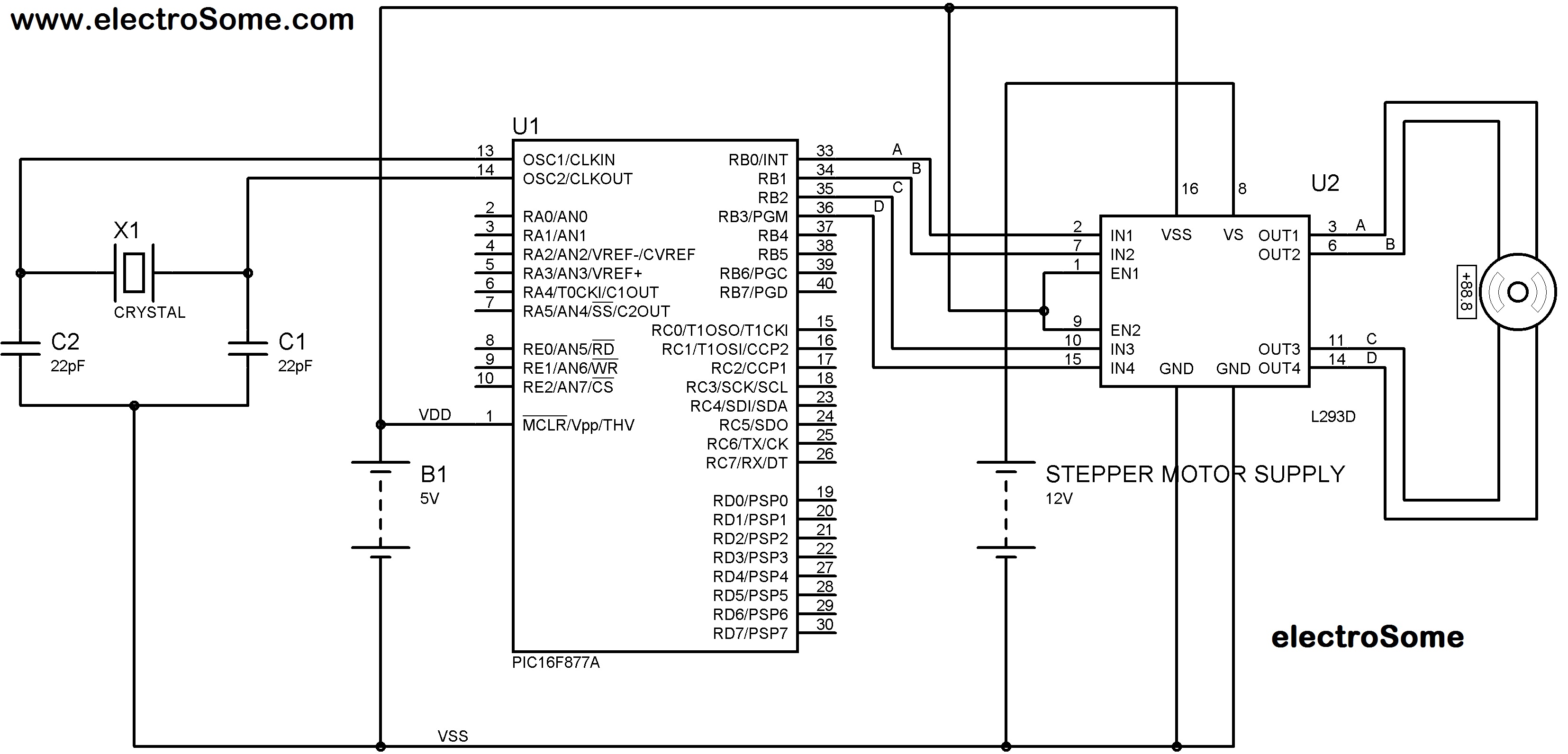
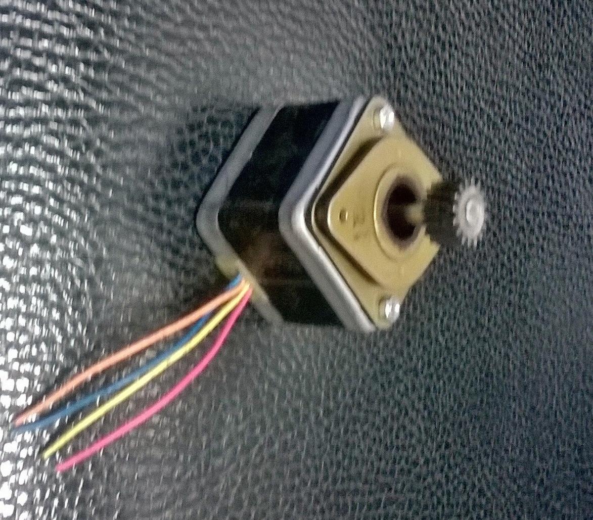
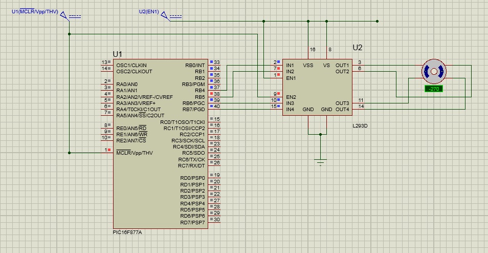
This time I am trying to work with a bipolar stepper motor. I have interfaced it to the PORT B of PIC16F877A through a L293DNE chip in the middle.
I am trying to rotate in the clockwise as well as anticlockwise direction. Twice in each direction actually, the problem is it doesn't work as it should. It just keeps jostling in both the directions. That is it gives one jerk in the clockwise direction ,not a step, and the other in the reverse direction.
It worked for a while before. We increased the no of iterations and it started this erratic behavior again.
I am using a 9V battery for the controller and a 12V battery for the motor.

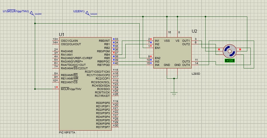
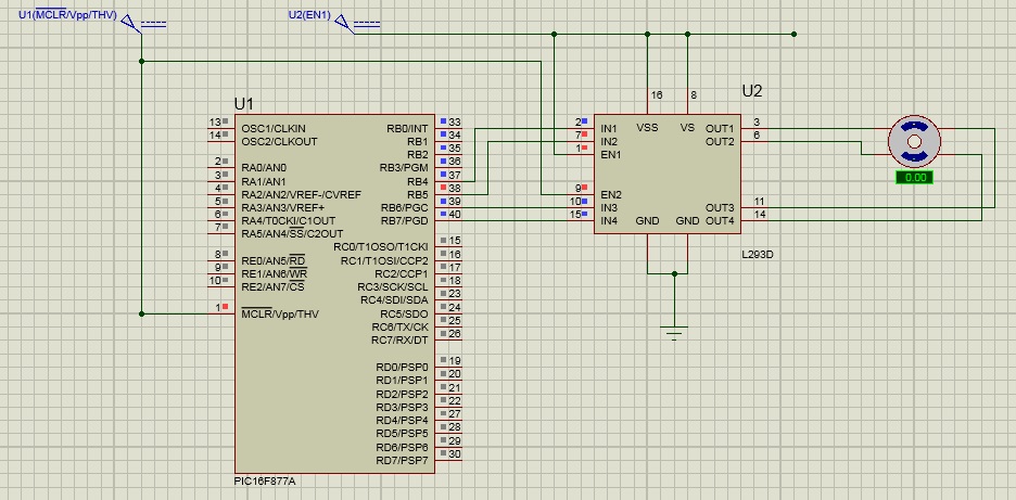
Everything is fine with the circuit, I have tried everything on Proteus which shows the expected ideal behavior but the hardware doesn't.

Help is direly needed as I have to submit this project by tomorrow and everything depends on the working of the motor.

Thanks in advance. Waiting eagerly for HELP!
 

Hi,

Post your schematic.
Post your code.

Klaus
 

Okay guys here is the schematic I am using.


Instead of using the port shown in the circuit I am using last four pins of PORTB. That's it. I am posting the circuit diagram as well as the proteus snapshot. And this is the sequence that i am following which made it move flawlessly but only for sometime.
Code:
PORTB=0x80;   //FORWARDDDDD
delay_ms(500);
PORTB=0x40;   
delay_ms(500);
PORTB=0x20;  
delay_ms(500);
PORTB=0x10;  
delay_ms(500);
It suddenly started working as per the behavior and made the happiest man on earth but then all of a sudden reverted to its former behavior making me the saddest again, I am perplexed, i have tried everything, I have tried interfacing it using ULN2803, i brought a brand new Unipolar Stepper motor with so much expectations, which did not even move.
And now I am disappointed as hell.

- - - Updated - - -

Please Help!!!
the problem is not that i dont know about the circuit or the interfacing, I have a fellow trainer in another center who has worked on unipolar stepper motors before, I took his ideas and tried that as well but it didnt work.

The bipolar stepper motor then started working as well but then it just keeps returning to its unwanted behavior i.e.
One jerk in one direction then one jerk in the reverse direction,

I dont know what is happening.
 
Last edited by a moderator:

Hi,

Your sequence 0x80, 0x40, 0x20, 0x10 most probably is not correct. (At least it makes no sense to me)

Read about full step or half step sequence.

Klaus
 

Sir please trust me. I know what I am doing. The only thing that i am not able to understand is the behavior of the motor. The sequence is correct according to the connections made to the L293DNE and it is meant to rotate the motor in the anticlockwise direction.
 

Please clarify if you are talking about unipolar or bipolar stepper motor and which driver you are using. The second schematic (L293 with unipolar stepper) is clearly wrong.

In case of the bipolar stepper motor, please clarify also the meaning of terminal A, B, C, D. Which are connecting to a coil, each?
 

It starts with the first step and comes back in the reverse direction and then keeps doing it in a loop.
 

Hi,

Sir please trust me. I know what I am doing. The only thing that i am not able to understand is the behavior of the motor. The sequence is correct according to the connections made to the L293DNE and it is meant to rotate the motor in the anticlockwise direction.

So the problem is not your code, not the sequence and not your wiring.

What recommendations are you willing to accept?

Like it or not:
My opinion. (I don't say I'm perfect. My opinion my be wrong)
An immediate change from 0x80 to 0x40 completely reverses the flux in one coil. (According your schematic)
But this means the motor should move, but you don't give it a direction by magnetising the other coil.
So it randomly moves forward or back.

Please refer to a document about your circuit and code (sequence).
Please give information wether you want to use full step or half step mode.

Klaus
 

I am working with the Bipolar stepper motor. it has four wires with orange, yelloow, blue, pink colors.
And honestly i dont know which one of them is A, B, C, D respectively.
Okay and here is the schematic that i am using.


- - - Updated - - -

Friend(Klaus) I respect you a lot. I have seen you helping many people and been following your posts forever.

I agree to whatever you say but it should not have worked even for once if what you say is right. And I have tried it with many sequences as well, But nothing made any difference.

- - - Updated - - -

- - - Updated - - -

Here is the motor that i am using. As you can see there are four wires. Can you please help me in identifying the wires.


Hi,

And honestly i dont know which one of them is A, B, C, D respectively
But this is the first thing you need to do:

Use a ohmmeter and find out what pair of wires are one coil.
(Low ohmic is one coil, high ohmic are different coils)

*****
The right schematic of your post#4 is not valid. It confuses.

*****
it should not have worked even for once if what you say is right.
I said randomly. This means sometimes the operation is correct, sometimes not.
So it randomly moves forward or back.
It may work .....by accidence. But expect no torque.

Klaus
 

Use an ohmmeter to determine which wires belong to one coil. My guess is that the adjacent wires belong to a coil. In this case your sequence would work if you change it e.g. to 0x80, 0x20, 0x40, 0x10.
 

Hi,

0x80, 0x20, 0x40, 0x10.
Yes. This is full step mode, one direction, full sequence.
Change in coil1, then change in coil2 then coil1....and so on.

in opposite this: (I doubt this works)
0x80, 0x40, 0x20, 0x10.
Change in coil1, change in coil1 again, then change in coil2 then coil2 again...

Klaus
 

Hi,

Can work when changing coil terminals, e.g. B<->C.
Correct. I´m still confused with schematic of post#4 where A and B clearely go to the same coil.


Klaus
 

You will need to put capacitors on the coils so that the drive transistors may not go bad when the current is switched off.

You need to mark the wires ABCD or something like that; interchanging a pair may be ok but not individual ones.
 

Thank you so muchhhhh for extending this much amount of support to me. I love you all guys. As soon as I reach the office I will do identify the wires.
And the schematic that doesn't seem to be right is the one which is widespread on the internet. So I decided to use it.
But if you have a better way of interfacing bipolar stepper with pic microcontroller using l293dne then that may help me a lot.
And what is the next thing I have to do after identifying the wires.
And I need to be sure here. I will use multimeter in ohmic mode and test the wires. The two wires with less resistance are A and B right? And the other two are C and D.
Please reply soon.

- - - Updated - - -

I will change the sequence as well and give it a try. Will revert with an update. But please if anyone can help mw with the schematic that will be a great help. I want to wrap this up today itself. I am counting on you guys.

- - - Updated - - -

Guys please look at the schematic in post #10 as well. Is it correct? And how will I come to know about low ohmic and high ohmic? Wouldn't it show resistance with all the wires taking any two at a time?

- - - Updated - - -

Guys I have identified the wires, orange and blue make one coil and yellow and pink make the other. And as far as I am concerned we can label them in any way right? Orange and blue can be A and B and yellow and Pink can be C and D right?
Now how to connect them to the L293Dne?
Or i should alter the sequence, i.e. 0x80,0x20,0x40,0x10;
I will give it a try. And update.

- - - Updated - - -

Guys I interchanged the B and C terminals and to my surprise it started working. But all of sudden it has returned to the same behavior. It is irritating me a lot, as it is hell bent on doing this only. Now its two steps CW and two steps ACW.

- - - Updated - - -

I don't know whats wrong. The motor runs for a little while then it doesn't.
I am making it rotate in ACW direction for four times and then in CW for the same four times. It starts the work, and goes in both the directions with no. of times mentioned. But this happens only once or twice then it starts doing the same thing.
Please help me!

- - - Updated - - -

Eagerly waiting

- - - Updated - - -

Now I am rotating it two times in both the directions, it works perfectly in the beginning then while coming back second time, it gives up and starts jerking forward and backward.
Need urgent help!!!
 

Hi,

actual schematic. actual code.

Klaus
 

Okay Klaus here is the actual schematic in Proteus and the actual code. as you can see I have interchanged the B and C wires and the motor works well in the Proteus. I wish it could work in the same way in real. Please tell me brother it will work well in real as well.


Code C - [expand]
1
2
3
4
5
6
7
8
9
10
11
12
13
14
15
16
17
18
19
20
21
22
23
24
25
26
27
28
29
30
31
32
33
34
35
36
37
38
39
40
41
42
43
44
45
46
47
48
void main() 
{
trisB=0x00;
PORTB=0xF0;
while(1)
{
PORTB=0x80;   //FORWARDDDDD
delay_ms(500);
PORTB=0x40;
delay_ms(500);
PORTB=0x20;
delay_ms(500);
PORTB=0x10;
delay_ms(500);
 
PORTB=0x80;   //FORWARDDDDD
delay_ms(500);
PORTB=0x40;
delay_ms(500);
PORTB=0x20;
delay_ms(500);
PORTB=0x10;
delay_ms(500);
 
delay_ms(1500);
 
PORTB=0x10;   //BACKWARD
delay_ms(500);
PORTB=0x20;
delay_ms(500);
PORTB=0x40;
delay_ms(500);
PORTB=0x80;
delay_ms(500);
 
PORTB=0x10;   //BACKWARD
delay_ms(500);
PORTB=0x20;
delay_ms(500);
PORTB=0x40;
delay_ms(500);
PORTB=0x80;
delay_ms(500);
 
delay_ms(1500);
 
}
}


- - - Updated - - -

I am waiting for you Brother. I need to make it work today itself.
Now the problem that it works but not continuosly? Why doesn't it work continuously, is the motor getting heated up? Nothing goes wrong with the L293DNE chip, it remains normally warm but not hot.

Helppppp!
 
Last edited by a moderator:

How long it runs before it finally stops? You can touch the rotor and feel whether it is free or under brake. If you power off and restart immediately, does it work fine? How many rotations per min it is currently giving (not from the software end; measure at the shaft).
 

Status
Not open for further replies.

Part and Inventory Search

Welcome to EDABoard.com

Sponsor

Back
Top