Continue to Site

Welcome to EDAboard.com

Welcome to our site! EDAboard.com is an international Electronics Discussion Forum focused on EDA software, circuits, schematics, books, theory, papers, asic, pld, 8051, DSP, Network, RF, Analog Design, PCB, Service Manuals... and a whole lot more! To participate you need to register. Registration is free. Click here to register now.

Troobleshooting 450w amplifier

Status
Not open for further replies.

Enzy

Advanced Member level 1
Joined
Mar 20, 2016
Messages
488
Helped
2
Reputation
4
Reaction score
2
Trophy points
18
Activity points
4,607
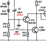
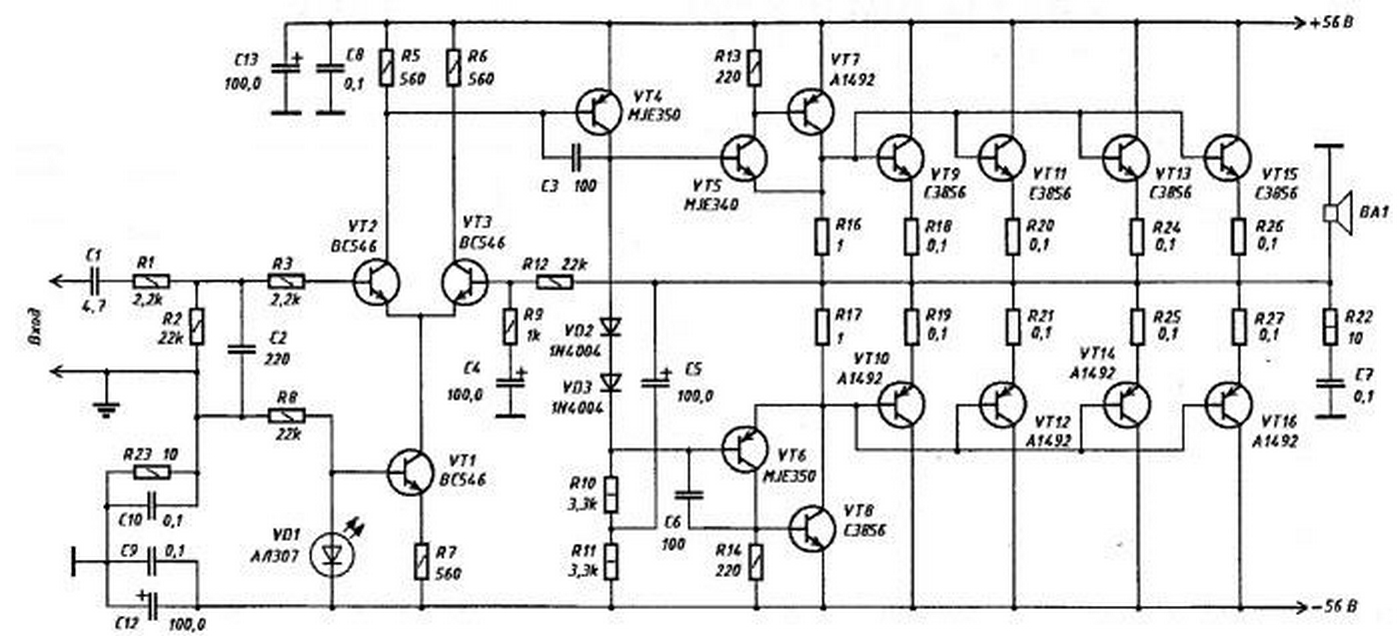
I build this amplifier circuit last-night I didnt add all the transistors I only added a pair for testing I used 2SC3856 and 2sa1216 for T1,T2 and T3 I used bc547 I didn't have any bc546. I supplied the board with 40v +/- I herd sound out of the amp when I connected it up but it was sounding bad like when am amp is getting low voltage or when the center tap leg isnt connected at the power supply stage what I realized is after as while a part of the board burned a little then I unplugged it, only a trace burned away slightly, what I realized is that I didnt add the 5 ohm resistor on the transistors so I did that and it didnt smoke after that but it still played bad, I touched one of the bc547 and realized it was warm, actually getting hot in a way. Across the collector and emitter I was getting about 38v and I was wondering if thats the problem since that voltage is close to the limit, the only other 2 things in the circuit which isnt correct is is I think c5 is 100pf and I used a 102 because I didn't have a 101 and also the 2 1n4004 in series with the 3.3k resistors I used 1n4007 instead and I used a power supply with regulators for testing puroses only not sure where my problem is I don't remember where I got this schematic it was either here or a next forum where it was said to be functional and tested.


I etched this circuit also I used photoshop and saved it back to Jpeg and it actually attacked 2 transistor legs up on saving the file, not until I etched the board and assembled the parts I realized that it did that some how.
 

Is the amplifier supposed to produce 450 Whats or 450 Watts?
450 watts into 8 ohms needs a power supply that is about plus and minus 90V!
Bootstrap capacitor C5 is supposed to be 100uF, C6 is 100pF. C5 is supposed to boost the voltage swing of all frequencies but your 1000pF capacitor will boost only frequencies and distortion harmonics that are higher than you can hear.
Your schematic shows a typical Jpeg fuzzy smudge all over each part. I always save a schematic as a PNG file that looks neat and clean.
 

I didnt design it all the images are copied also its 450W into 4ohm at 56V but I used 40V to test it. So your saying the first thing I should do is change that cap from 102 to 101? Also you dont think its the bc547's that I used? Ill check around today to see if I cand find any shops that have it for sale, hopefully thats the problem.
 

I said that C5 is 100uF, not 100pF. C6 is 100pF. Elliot Sound Products has a 300W into 4 ohms subwoofer amplifier that is almost the same as the one you found, including a plus and minus 56V supply. It uses MPSA42 high voltage input transistors rated at Vcbo= 300V. Your BC547 is rated at only 45V.
 

Attachments

  • 450W amplifier capacitors.png
    450W amplifier capacitors.png
    94.8 KB · Views: 123

ok forgive me if I mixed up the values I didnt look at the schematic while building it I looked at the proteuous layout of it so I placed all the parts in the correct places but in that case I used a 1000pf capacitor at c6 instead of 100pf thats the closest I had and I was just trying to confirm if you think that thats whats causing the bad sound. Also I think I can find some of those mpsa42 and a mpsa92
 

When C6 has a value that is 10 times too high then at high audio frequencies the amplifier frequency response drops and the distortion will be high.
Digikey has thousands of MPSA42 and MPSA92 transistors in stock at very low prices.
 

Forgive my jest but reading that first message made me think:

" I built a bicycle, but I only had one wheel so I left one off. I couldn't find a saddle so I used a toilet seat instead. I couldn't find a pump so I left the tire flat - oh and the only pedals I could find were different sizes. Anyway, when I sit on it I fall off, what could be the problem?" :thinker:

Brian.
 
Ok then are you suppose to help in anyway?

- - - Updated - - -

with replies like that you can keep them to yourself.... thats not helpful... I have seen many times where person dont have a specific part and a persons here tell them to use something close enough I even got the same advice here so If I was to use a capacitor which is 101 and I found a 102 which is have to be the closest why make a big deal if your so smart explain why in this case that replacement wont work isnt that the point of the forum or your too smart to figure out how to explain when someone is wrong and what can be done.
 

I have seen many times where person dont have a specific part and a persons here tell them to use something close enough I even got the same advice here
Nobody here told you to replace the 100pF (101) capacitor with a 1000pF (102) capacitor because they are not close.

If I was to use a capacitor which is 101 and I found a 102 which is have to be the closest
No they are not close. 101 is 10 with ONE zero at the right end making it 100pF. 102 is 10 with TWO zeros at the right end making it 1000pF (1nF). 103 is 10nF, 104 is 100nF and 105 is 1uF.

explain why in this case that replacement wont work.
I explained that it will cut high audio frequencies and cause distortion of high frequencies to be high.
 

I didn't tell you that you told me to replace 101 with a 102 I was speaking to that other person and It was an example saying that at time persons here meaning the forum itself will tell you that you can use can replace components at times, so I am a newbie to Electronics to a level so I am short on 1 capacitor labeled 101 and I have a 102 don't you think I would think that thats the closest so I tried it thats all I was saying why am I to be mocked for that is something wrong with trying what I did.

- - - Updated - - -

I already saw your explanation and understood what you said and said I will try to get the correct value its just this other guy "betwixt " replying by saying something that makes no sence to my topic.
 

Hi,

its just this other guy "betwixt " replying by saying something that makes no sence to my topic.

Why do you think it makes no sense?

I say it in other words:
Use the correct parts, the correct values and the correct part count...and you will have a bigger chance that your amplifier is working correctely.

A feedbacked amplifier is a sensitive curcuit. Selecting another transistor changes (may change) loop gaing an therefore may lead to instabilities = oscillations.
The same is with capacitors and resistors.
Additionally you replaced a diode. This diode ensures proper bias current of the output transistors and compensates temperature drifts.
Too high bias current causes heating, too low bias current causes distortion and may lead to oscillations.

So if you think if somebody recommends "to use the correct parts like in the schematic" makes no sense, then it will be difficult to make your amplifier working properly.

Klaus
 

I didn't mean offense but look you were querying why it didn't work and at the same time making ststements like:
I didnt add all the transistors I only added a pair for testing I used 2SC3856 and 2sa1216
so you missed (guess) 6 transistors and 6 resistors out of the design and the two you did fit were the wrong types.
I used bc547 I didn't have any bc546
Did you notice their voltage ratings are significantly lower than BC546 and in fact less than the amplifier supply voltage?
I supplied the board with 40v +/-
The component values are for +/- 56V as shown on the schematic.
I think c5 is 100pf and I used a 102 because I didn't have a 101
'102' is ten times bigger in value than '101' but as Audioguru pointed out, it should almost certainly be 100uF not 100pF anyway. (1,000,000 times bigger!)

The change of diodes is less of an error but you did remember to bond them to the heat sink didn't you? They are supposed to reduce the bias current when the output transistors warm up so you need to have the heat from them coupled to the diode body.

It wasn't a personal attack I made and I do understand you may be a novice at electronics but you ignored so many points in the design that it no longer had much chance of working at all.

Brian.
 

Hi,

The change of diodes is less of an error
-->
and also the 2 1n4004 in series with the 3.3k resistors I used 1n4007 instead
It depends. If he used ONE 4007 (1000V) instead of TWO 4004 (400V) (because of the increased voltage rating) then it surely makes a difference.

Klaus
 

I etched this circuit also I used photoshop and saved it back to Jpeg and it actually attacked 2 transistor legs up on saving the file, not until I etched the board and assembled the parts I realized that it did that some how.

Take heart, you are in the right way to learning. I too learnt the stuff the hard way:

100 pF is way too small, can't we just ignore it?

The fellow must have put two diodes in series because he was not having one with high reverse voltage.

If part of the board got burnt, then it is called planned obsolescence.

That it made some sound is proof of something is working. It is sound by design.

Only god can tell when a 100 means 100 uF and when another 100 means 100 pF.

Of course it is the fault of the computer!

(no offense meant to anyone)
 

Ok now thats a better reply but I looked at the bc547 and realized it had a lower voltage rating, thats why I used 40v +/- which I stated so that means I wouldnt send too much voltage to them.

for transistors I didnt use all the transistors on the output I only used 1 pair which I stated, I actually have TIP135 and TIP136 I didnt use them right away because I realized that there was a fault with the board in that the pins are too far apart to use TIP135 and 136. The transistors I used was also a recommendation from the guy I got the schematic from even though he didnt use them himself so that why I mentioned that I used them incase it was possible for it to be the problem also so I applied a little common sense to what I was doing.

When it came on to me using the wrong capacitor its because I really wanted to know if the design works because I want to build a couple of these amplifiers and in my country much parts arent avaliable so If I am to order online it will take a month before I receive them so with my novice self I was to use a 101 and the closest I could find was a 102 so I tried it to see if I would get it working to confirm that I could order all the correct parts.

I didnt bond the 1n4007 diodes to the transistors body how would I do that its not the standing type to-220 type transistors its the small 1amp diodes so I am not sure about the bonding process but for testing purposes also I didnt use a heatsink on the Pair of transistors I used and with that test they didnt get warm.

- - - Updated - - -

Hi,


-->

It depends. If he used ONE 4007 (1000V) instead of TWO 4004 (400V) (because of the increased voltage rating) then it surely makes a difference.

Klaus

So should I use only a single 1n4007 and then use a jumper to make the other section of the circuit remember its a pcb.
 

Hi,

So should I use only a single 1n4007 and then use a jumper to make the other section of the circuit remember its a pcb.
Best is to use the same parts like in the schematic.
Here (not for every application) you should use the same count of diodes as in the schematic. (It is not important that it can withstand 400V or 1000V, but the diodes should give the same thermal drift (like the power transistors) of about -2mV/°C per diode. 2 Diodes give about -4mV/°C)

And like Brian said: They should be thermally coupled to the power transistors. They are used for temperature drift compensation...obviously they can´t compensate the temperature drift if they don´t have the same temperature (diodes and power transistors).

Klaus
 

I too learnt the stuff the hard way:
Are your answers in this post a joke?

100 pF is way too small, can't we just ignore it?
It is the frequency compensation capacitor used in all opamps and audio amplifiers. It is the most important capacitor in the circuit because it prevents the amplifier from oscillating at the high frequency where phase shifts in the amplifier cause high frequency negative feedback to become positive feedback. Without the 100pF capacitor then the amplifier has some voltage gain at the oscillation frequency but with the capacitor its gain is less than one at that high frequency so it does not oscillate.

The fellow must have put two diodes in series because he was not having one with high reverse voltage.
Two diodes are used to set the bias in the output transistors to class-AB. With only one diode then they would be biased in class-B that produces horrible crossover distortion. The diodes are never reverse biased so their maximum rated voltage does not matter.

Only god can tell when a 100 means 100 uF and when another 100 means 100 pF.
I don't use god, instead I use experience. On a sound system website, Elliot Sound Products, I found an identical amplifier circuit with the same supply voltages, the same 100uF and 100pF capacitors, the same two diodes and many resistor values the same. Its transistors were different.

- - - Updated - - -

on the output I only used 1 pair which I stated, I actually have TIP135 and TIP136 ..... The transistors I used was also a recommendation from the guy I got the schematic from even though he didnt use them himself ..... I applied a little common sense to what I was doing.
No and no. The circuit uses ordinary power transistors. The TIP135 and TIP136 are DARLINGTON dual transistors which are COMPLETELY DIFFERENT and will not work properly. It is common sense to compare replacements on their datasheets.

I didnt use a heatsink on the Pair of transistors I used and with that test they didnt get warm.
Because they were very different to what is needed then they did not work properly.

EDIT and updated. Posted by Enzy:
So should I use only a single 1n4007 and then use a jumper to make the other section of the circuit?
No. With the darlington transistors you used then 4 diodes are needed. Look up "crossover distortion" that I talked about in this post.
 

Attachments

  • 450W amplifier.png
    450W amplifier.png
    279.8 KB · Views: 194
Last edited:

This thread is going a bit crazy.

Audioguru - I think you interpreted c_mitra's post in the wrong way - they were giving examples of mistakes, not design guidelines!
Certainly the TIP transistors will not work, at least without extreme cross-over distortion. Adding an exta pair of diodes might bring it back to class A at low levels but at the same time it would reduce available current down the bias chain.

Enzy - the diodes are there to drop a fixed voltage and the primary considerations are they drop the same amount as the base-emitter junctions of the output transistors and are made of the same material, silicon in this case. When silicon warms up it becomes more conductive so in the case of the output transistors it would make more current flow though them. That in turn makes them generate more heat and a destructive cycle starts, we call it "thermal runaway". The simple way of fixing it is to bond the diodes, which set how much current flows through the transistors to the transistors or their heat sinks. As the transistors warm up, the diodes do so at the same time and as they conduct more they reduce the bias current and stabilize it. Usually the diodes are either epoxy glued to the heat sink or pushed against it and bedded in heat sink compound.

The reason the TIP135 and TIP136 will not work is they are "Darlington" transistors. These are essentially two transistors in one package, wired so the current through the first one biases the second one. It results in a transistor with very high gain but at the same time it has a higher saturation voltage and needs twice as much bias voltage. The circuit will not produce the extra bias voltage it would need so the transistors would not conduct.

I find it strange that the two circuits are so similar, I suspect one was copied from the other. The LED constant current is unusual in an audio amplifier to say the least. If I had to build one or the other I would choose the Elliot one every time.

Brian.
 

Hi,

The LED constant current is unusual in an audio amplifier to say the least
Maybe unusual, but the LED has it's benefit: A LED creates less noise than a typical zener.

Klaus
 

Well the information I got was to use Tip35 and Tip36 but I didnt because as I said the spacing for the pins on the board was too wide for them so instead I used 2sa1216 and 2sc2922 since the darlington transistors wont work what about the ones I am now using can those work?

Based on how the pcb is designed there can be no heat sink on the diodes or even if I can fit a heatsink to them it wouldnt be able to touch the heatsink on the transistors.

before I proceed to fixing this amplifier does anyone have a working schematic with a pcb layout of an amplifier say 400 watts or more.
 

Status
Not open for further replies.

Similar threads

Part and Inventory Search

Welcome to EDABoard.com

Sponsor

Back
Top