Continue to Site

Welcome to EDAboard.com

Welcome to our site! EDAboard.com is an international Electronics Discussion Forum focused on EDA software, circuits, schematics, books, theory, papers, asic, pld, 8051, DSP, Network, RF, Analog Design, PCB, Service Manuals... and a whole lot more! To participate you need to register. Registration is free. Click here to register now.

Help with a temperature detection circuit

Status
Not open for further replies.

DoctorMckay

Newbie level 3
Joined
May 6, 2016
Messages
3
Helped
0
Reputation
0
Reaction score
0
Trophy points
1
Activity points
33
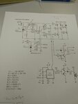
Ok, I have a circuit that lights up different LEDs depending on the temperature the sensors detect.
If it detects a temperature between specific limits, lets say 15º and 30º Celsius the green LED should light up. If it would detect something below 15º the Yellow LED would light up and if it would detect something above 30º the Red LED would light up.

Problem is I do not know how to regulate the limits at which the LEDs light up.
I suppose it has something to do with changing PG, R3, R4 and R5, but I do not know how to calculate the resistors.

Could somebody explain it to me?

PD: Ignore all the nonsense written by pencil. Also all the voltages entering the circuit are equivalent to 9 volts DC. The LEDs are Yellow, Red, Green, from left to right.
 

Attachments

  • photo_2016-05-06_08-33-28.jpg
    photo_2016-05-06_08-33-28.jpg
    84.6 KB · Views: 73

Ok, so if I want to edit the temperature’s limits I just have to measure the voltages at the pins you said when the Green LED lights up or lights off according to the temperature registered by the sensors and try setting the resistors according to the results. Thanks for the explanation.
Now I have another question, if I take RP and IC5 out from the circuit I should be able to set the maximum and minimum limits for the LEDs manually by adjusting the resistors, should not I?
VR3 and VR5 are the voltages that set the limits, so, for example, if I wanted the limits to be 15 º Celsius and 30º Celsius I should change R3, R4 and R5 right? Is there an equation for their calculus?
PD: 15 and 30 were just values I gave as examples, I still do not know when the Green light will be lighted up, so, I would appreciate if the explanation you give me used “X” and “Y” as values.
photo_2016-05-06_09-56-01.jpg
 

Hi

bring the sensor to 15°C and measure the voltage on IC2 pin6
bring the sensor to 30°C and measure the voltage on IC2 pin6

then according ohm´s law (or by voltage divider calcualtion) calculate the values for R4 and R5 to meet both values measured before.

Klaus

- - - Updated - - -

Hi,

Rp and IC5 are for precise and stable thresholds.
Supply voltage is not that stable, therefore don´t expect good performance.

***
VR3 and VR5 are the voltages that set the limits, so, for example, if I wanted the limits to be 15 º Celsius and 30º Celsius I should change R3, R4 and R5 right? Is there an equation for their calculus?
PD: 15 and 30 were just values I gave as examples, I still do not know when the Green light will be lighted up, so, I would appreciate if the explanation you give me used “X” and “Y” as values.

Funny question...
bring the sensor to X°C and measure the voltage on IC2 pin6 --> VR5
bring the sensor to Y°C and measure the voltage on IC2 pin6 --> VR3

then according ohm´s law (or by voltage divider calcualtion) calculate the values for R4 and R5 to meet both values measured before.

***
To ease calculations: Don´t change R3.

Klaus
 

Status
Not open for further replies.

Similar threads

Part and Inventory Search

Welcome to EDABoard.com

Sponsor

Back
Top