niccoh
Junior Member level 1
I have a simulink model (using Comm. Toolbox / DSP blocks) I have built that will do QAM modulation just fine with pulse-shaping (using Root-Raised Cosine Filter). I'm trying to get a Baseband signal to RF for time-domain analysis for a RF PA.
I need an LTE like signal with a high PAPR. So I am using an OFDM modulation on 16-QAM coding. 18MHz symbol rate, with 1200 data carries for ~150kHz OFDM carrier spacing. Then I have some guard bands. My problem is I can't seem to up-sample and down-sample the OFDM output (which I need to if I want to do a conversion to 800MHz or 2GHz).
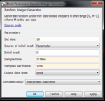
Here's my block diagram in simulink and other parameters...


Here you can see the output spectrum and the constellation mapping. The OFDM demodulated outputted is forming rings or something and I'm not understanding why. I've introduced no RF impairments, just up/down sampling using FIR interpolate/decimators. Upsample of 25 and then downsample of 25 at output of DC mixer.
Everything was working with my QAM16 setup and RRC filtering without the interpolate/decimator. But again I need a time domain / RF spectrum at 800MHz - 2GHz.


Thanks for any help!
I need an LTE like signal with a high PAPR. So I am using an OFDM modulation on 16-QAM coding. 18MHz symbol rate, with 1200 data carries for ~150kHz OFDM carrier spacing. Then I have some guard bands. My problem is I can't seem to up-sample and down-sample the OFDM output (which I need to if I want to do a conversion to 800MHz or 2GHz).
Here's my block diagram in simulink and other parameters...


Here you can see the output spectrum and the constellation mapping. The OFDM demodulated outputted is forming rings or something and I'm not understanding why. I've introduced no RF impairments, just up/down sampling using FIR interpolate/decimators. Upsample of 25 and then downsample of 25 at output of DC mixer.
Everything was working with my QAM16 setup and RRC filtering without the interpolate/decimator. But again I need a time domain / RF spectrum at 800MHz - 2GHz.


Thanks for any help!