Continue to Site

Welcome to EDAboard.com

Welcome to our site! EDAboard.com is an international Electronics Discussion Forum focused on EDA software, circuits, schematics, books, theory, papers, asic, pld, 8051, DSP, Network, RF, Analog Design, PCB, Service Manuals... and a whole lot more! To participate you need to register. Registration is free. Click here to register now.

Testing out an amplifier chip

Status
Not open for further replies.

Enzy

Advanced Member level 1
Joined
Mar 20, 2016
Messages
488
Helped
2
Reputation
4
Reaction score
2
Trophy points
18
Activity points
4,607
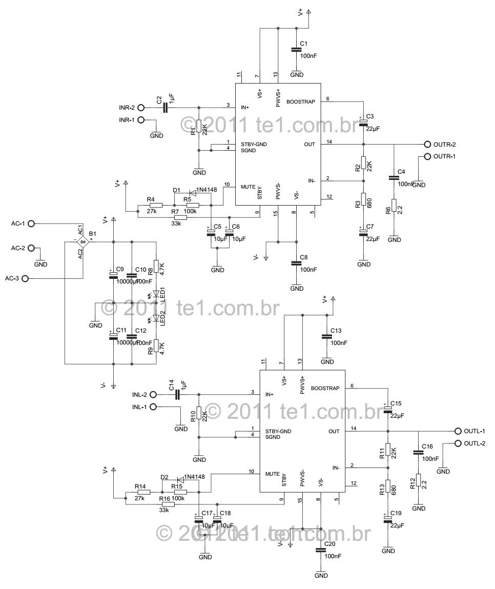
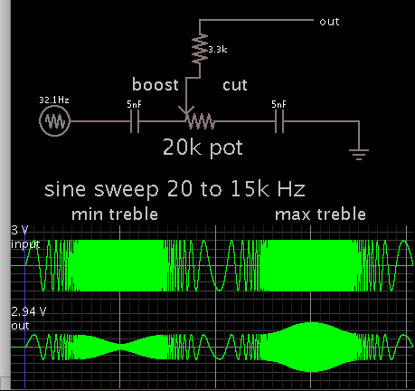
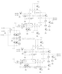
I decided to try out this amplifier chip, I want to try the basic schematic, I want to use it to play 3 speakers 2 8 inches and a 10inch speaker and a tweeter. should I modify anything in this circuit for it to play good. all speakers are in one box I am doing this test because I want to see if its good enough to use as a guitar amps because I want to build one next month.

- - - Updated - - -


I'm afraid my psychic amplifier hat needs new batteries so I'll have to rely on you to tell us what the amplifier IC actually is.

Brian.
 

its tda7293
 

Something that you require to check is what are the datasheet's input-signal voltage requirements to produce a full power output.
It has been over 30 years that I dealt with electric guitars, but if I remember properly, they produce something like 50 mV of output, which may be insufficient to drive this chip.

Once that you know what is the guitar voltage, and what is the input signal requirements, then you can then build a pre-amp with the proper gain. Tone controls and or effects can be added at that stage.
 

Well It should be more universal as it might be used for several guitars, but before I reach that stage what do you think about the Tda7293 amplifier chip and the schematic I posted does it look like a good amp do you think any improvements can be done to it
 

It looks good to me. Be careful of the high voltage supply, you probably want 100V (+50V, -50V) and make sure you use a large heat sink!

Watch out for the speaker cross-over design, you can't just wire the loudspeakers across each other, you have to filter the frequency bands fed to them for their own safety and to prevent the amplifier load impedance being too small.

Brian.
 

The third speaker has no amplifier.
An electric guitar pickup needs a preamp with a very high impedance like this one to produce the high frequency peak to make the "twang" sound:
 

Attachments

  • guitar preamp.PNG
    guitar preamp.PNG
    15.4 KB · Views: 96
  • Guitar pickup peak.PNG
    Guitar pickup peak.PNG
    73.1 KB · Views: 97

I want to use it to play 3 speakers 2 8 inches and a 10inch speaker and a tweeter.

Your amplifier appears to be a stereo one with two channels. But how you are planning to drive the remaining 2 speakers? What about the cross over network?
 

Ok so this preamp is good enough for me to make for guitars?

I have irfz44n I would replace the j201 in the diagram with it if thats ok.

Also what if I wanted to power the preamp by taking power from the same amplifier its powering by using a 9v regulator.

and also wouldnt the amp need a tone control? I would have to build that seperate from the preamp.

- - - Updated - - -

I actually build this amp lastnight, but only one side. I was planning to build a RC low and high pass filter and connect to each speaker.
 

The J201 is a junction FET
The IRFZ44 is a MOS FET

Their method of biasing them is completely different.
 

Ok I didnt realize, so as I asked earlier If I was to use that I would need a tone control circuit differently, does anyone have a good but simple one I could try.
 

Most "guitar speaker systems" do not have tweeters because an electric guitar does not produce high frequencies and band players and listeners cannot hear high frequencies. Here is the frequency response of a typical electric guitar speaker system that drops sharply above 3kHz. The peak at 2kHz is "cone breakup" that occurs in most speakers. A crossover network usually eliminates this peak when a tweeter is added.
 

Attachments

  • electric guitar speaker system response.png
    electric guitar speaker system response.png
    169.6 KB · Views: 131
Ok I didnt realize, so as I asked earlier If I was to use that I would need a tone control circuit differently, does anyone have a good but simple one I could try.

This post is not intended to counteract Audioguru's excellent advice. Since you ask about a tone control, here is the treble portion of a Baxandall filter. It cuts and boosts higher frequencies.

You'll need to play with values, to make it give the desired response with your amplifier or pre-amplifier.

6577081300_1462385338.png
 

First try to define ( by commercial comparison) your expectations in a value for;
-equivalent input noise and signal range
-THD
-Output peak power
-RMS power, and temperature rise from losses.
-Load impedance range vs power
and frequency response deviations

If you can afford to avoid poor choices of ceramic by replacing the double bar non polar caps with plastic types and polarized ones with solid electrolytic types,... These are more ideal for preventing THD in the cap from large voltage swings and reducing supply noise with a lower ESR during max current surges.

Otherwise, you may not know the difference. PCB complementary trace layout and grounding layout with good power supply regulation at peak impulse current are also important.
 

Status
Not open for further replies.

Similar threads

Part and Inventory Search

Welcome to EDABoard.com

Sponsor

Back
Top