wfg42438
Member level 3
- Joined
- Jun 29, 2015
- Messages
- 54
- Helped
- 0
- Reputation
- 0
- Reaction score
- 0
- Trophy points
- 6
- Location
- California
- Activity points
- 620
Hello Everyone,
Below is a simple multiplexer design i wanted to implement, please let me know if you see anything wrong with my thought process
Goal:
If a seven segment display shows value 6: output 500Hz tone,
For a value of 7 utput 2kHz tone
or if a value of 8 is displayed: output a 5kHz tone
The three tones described earlier have already been designed using 555 timers in the astable mode and they work
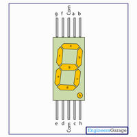
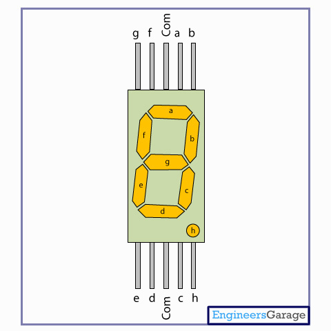
I noticed the following segments of the 7 segment display are shared by the three values values: f, a, & b
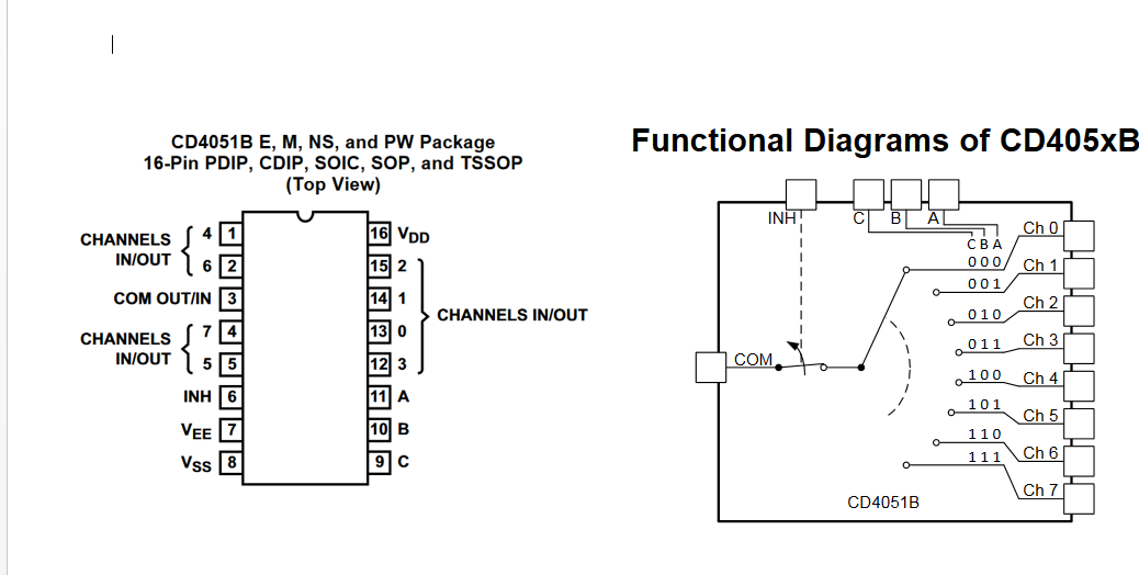
For a value of 6 we have the following: f=1, a=1, b=0 ----> therefore we have the value 110 ----> 500 Hz tone connected to Ch.6
For a value of 7 we have the following: f=0, a=1, b=1 ----> therefore we have the value 001 ----> 2kHz tone connected to Ch.1
For a value of 8 we have the following: f=1, a=1, b=1 ----> therefore we have the value 111 ----> 5kHZ Hz tone connected to Ch.7
Therefore we take a lead from pin "f" (either before or after the resistors going to the seven segment displays) to C of the MUX,
a lead from pin "a" of the display to B of the MUX
a lead from pin "b" of the display to A of the MUX
Once this is done we should see no tone for values 0-5 and three distinct tones for 6, 7 & 8
Please note this was all done under the assumption that when a segment of the display i shut off its a logic low and when lit its considered a logic high
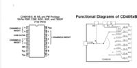
Link to Datasheet: https://www.ti.com.cn/cn/lit/ds/symlink/cd4051b.pdf
Below is a simple multiplexer design i wanted to implement, please let me know if you see anything wrong with my thought process
Goal:
If a seven segment display shows value 6: output 500Hz tone,
For a value of 7
utput 2kHz toneor if a value of 8 is displayed: output a 5kHz tone
The three tones described earlier have already been designed using 555 timers in the astable mode and they work
I noticed the following segments of the 7 segment display are shared by the three values values: f, a, & b
For a value of 6 we have the following: f=1, a=1, b=0 ----> therefore we have the value 110 ----> 500 Hz tone connected to Ch.6
For a value of 7 we have the following: f=0, a=1, b=1 ----> therefore we have the value 001 ----> 2kHz tone connected to Ch.1
For a value of 8 we have the following: f=1, a=1, b=1 ----> therefore we have the value 111 ----> 5kHZ Hz tone connected to Ch.7
Therefore we take a lead from pin "f" (either before or after the resistors going to the seven segment displays) to C of the MUX,
a lead from pin "a" of the display to B of the MUX
a lead from pin "b" of the display to A of the MUX
Once this is done we should see no tone for values 0-5 and three distinct tones for 6, 7 & 8
Please note this was all done under the assumption that when a segment of the display i shut off its a logic low and when lit its considered a logic high
Link to Datasheet: https://www.ti.com.cn/cn/lit/ds/symlink/cd4051b.pdf