Continue to Site

Welcome to EDAboard.com

Welcome to our site! EDAboard.com is an international Electronics Discussion Forum focused on EDA software, circuits, schematics, books, theory, papers, asic, pld, 8051, DSP, Network, RF, Analog Design, PCB, Service Manuals... and a whole lot more! To participate you need to register. Registration is free. Click here to register now.

MOSFET Amplifier, IRF530/9530 with BJT drivers

Status
Not open for further replies.

Mnt

Member level 5
Joined
Mar 20, 2016
Messages
91
Helped
2
Reputation
4
Reaction score
2
Trophy points
8
Activity points
721
Hi,

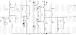
this is my DIY, its an audio amplifier with two 23V rails (2x 17.5V AC)(260W transformer)

I'm glad to hear any opinions :cool: This is 20khz square.

Firstly i planned to use only bc546+556 for the small signal transistors, but im out of them and i used 2n5551+5401+my last bc556

THD 0.05710% @ 1khz and 0.17069% @ 20khz. This is measured in TINA.
In Multisim this is 10 times better -> 0.006% 1khz & 0.020% 20khz.

edaboard1.PNG

edaboard2.PNG

edaboard3.PNG
 
Last edited:

Look, look I changed the sch, i had a problem with my previous and dont know why.
One transinstor failed when I plugged it. There's is no problem with this and its awsome :) :bsdetector:

NEW_SCH.PNG

NEW_FFT.PNG

:thumbsup:

- - - Updated - - -

NOw I can measure the current easily via R10 with a voltmeter :D
 

Oops, I forgot to upload some camera shots.

Sound brilliant, but need to redesign it for a little higher voltage -> +-42V :bsdetector:
and this will require me to use a current limiter because im designing it for 2-16 ohm range.

=> worst case @ 2 ohm == 42/2*42 = 882W
this needs to be limited to 250W :lol:

with 42V rails one can get 110.3W @ 16 ohm peak power :)

I have a 260W transformer, do you think it will handle two channels with total peak power -> 500W ?? :?:

DSC05702.JPG

DSC05703.JPG

DSC05704.JPG

DSC05705.JPG

DSC05706.JPG

I am using BC548C for LTP transistors/
 

I want to show you my next pending build's schematic.

now.PNG
 

I made your new schematic a positive image instead of the negative image, but I could not remove the chicken pox dots.
 

Attachments

  • amplifier.png
    amplifier.png
    22.3 KB · Views: 134

For class AB operation there's no thermal ru naway limiter on the main o/p xtors, such as you have in your 1st posted schematic...
 

I think there are some capacitors missing in the last design. I would imagine there would be considerable supply modulation fed back to the first stage so I would recommend you add some sizeable capacitors (>100uF) between the input stage supplies and ground.

Current limiting the supply in a class AB amplifier will hugely increase distortion, especially at high volume levels, if you need to limit the output power it would be better to soft clip the input signal or increase the negative feedback to reduce it's gain. And no, you can't squeeze 500W out of a 260W transformer! You can't even get 260W of audio out it when you take into account the circuit inefficiencies.

Brian.
 

I have seen many amplifiers with an under-sized power transformer and they play music and speech perfectly. But they cannot play a continuous tone at full power all the time. They also have undersized heatsinks for the same reason. The average power levels of music and speech are much less than the peak output levels then the amplifier produces good "music power" with an under-sized transformer and heatsinks.
 

What is "chicken pox dots" ? :laugh:

For class AB operation there's no thermal ru naway limiter on the main o/p xtors, such as you have in your 1st posted schematic...

I am using diodes instead vbe multiplier. They do the same job.

I think there are some capacitors missing in the last design. I would imagine there would be considerable supply modulation fed back to the first stage so I would recommend you add some sizeable capacitors (>100uF) between the input stage supplies and ground.

Current limiting the supply in a class AB amplifier will hugely increase distortion, especially at high volume levels, if you need to limit the output power it would be better to soft clip the input signal or increase the negative feedback to reduce it's gain. And no, you can't squeeze 500W out of a 260W transformer! You can't even get 260W of audio out it when you take into account the circuit inefficiencies.

Brian.

Yes there are two capacitors missing. I am not current limiting the input stage current.
These 22 ohms are for supply LP filters with the missing capacitors.

And for the watts I said the number with the inefficiencies included. I know there are heat dissip and waste of energy. :bsdetector:

- - - Updated - - -

Oh I understood what is "chiken pox" :D

- - - Updated - - -

This is my other sch, but i have a little issue with it, which is described in another thread
-> https://www.edaboard.com/threads/354537/#post1516677

R9 is 100ohm + 1k trim pot in series, in reality.

123a.PNG
DSC05726.JPGDSC05728.JPG
 

Thank you for turning off the Chicken Pox dots.

Your wiring is um, a mess. Oscillation is almost guaranteed with the capacitance and coupling between all the long wires and each wire has some series inductance. The high current wires are very thin then they must have a high voltage drop then the audio and oscillation modulates the supply voltage to the circuit and causes other problems.
 

Status
Not open for further replies.

Part and Inventory Search

Welcome to EDABoard.com

Sponsor

Back
Top