Eight
Member level 2
Hello.
I'm stuck working on a circuit, and I need some advice. I have a protoboarded circuit with a bunch of dual-supply amplifiers, and so it happens that I need a stable adjustable voltage reference that can span a few volts around GND i.e. +/- 5V. I don't need accuracy up to a millivolt, the important part is that the voltage is constant, stable and adjustable via a variable resistor (potentiometer). I've done some searching and I mostly found schematics for single-supply references. For example see the attached image below.
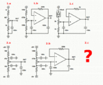
Circuir 1.a is a simple voltage divider. While this type of setup does offer an easy adjustable voltage, the problem is that it's very inaccurate and unstable especially when the system starts drawing higher current from it (drift). It gets better when the resistor values become lower, but also draws more current. So some people suggested that an additional buffer (voltage follower) be added to it.
Circuit 1.b shows such buffer present behind the voltage divider. The circuit has some additional decoupling/bypass caps for better stability, and it has also been suggested to add a resistor to the negative feedback loop to prevent oscillations when dealing with capacitive loads. There should be similar resistors on both opamp inputs. We can also use higher resistor values since the current is no longer an issue here. This setup works much better, but the circuit still has stability issues. For example, if the positive power supply rail encounters some noise, it will get amplified onto the reference volrage output.
Circuit 1.c shows another improvement. A constant current source is used on the voltage divider to eliminate positive rail supply noise.
Now all the circuits decribed so far are for single power supply. It happens that I am using a dual power supply of +/- 9VDC, and thus I need an adjustable voltage reference that can span for about 5V in each direction from the GND terminal. Circuit 2.a shows a dual-supply equivalent of the unstable circuit 1.a. Circuit 2.b is a dual-supply equivalent to 1.b with similar stability issues. What should I use to achieve dual-supply equivalent of circuit 1.c that has similar stability? I believe I can't use a constant current source between V+ and V- to eliminate power supply noise because if I eliminate it on the positive rail, it can still enter via the negative rail and vice-versa.
Suggestions?
Thanks in advance!


